Chris Keane
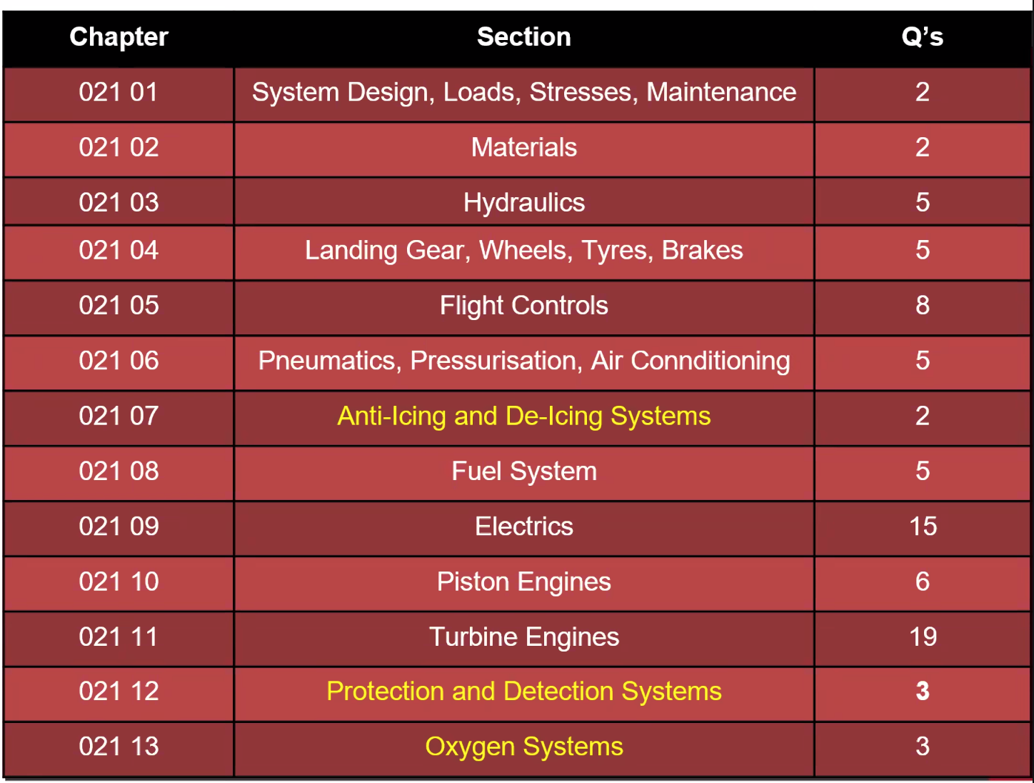
80 Questions / 2 Hours / Normally completed in 1 hour.
Subjects in yellow are not covered in the revision week (not enough time).
Stress and Fatigue
Aircraft parked on the ground, the upper part of the wing is subject to Tension, whilst the lower part of the wing is subject to compression.
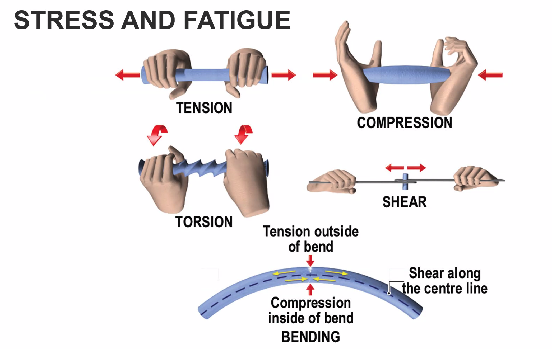
Learning Objects: Stress is the internal force per unit area inside a structural part as a result of external loads. Strain is the deformation caused by the action of stress on a material. It is normally given as the change in dimension expressed as a percentage of the original dimensions of the object
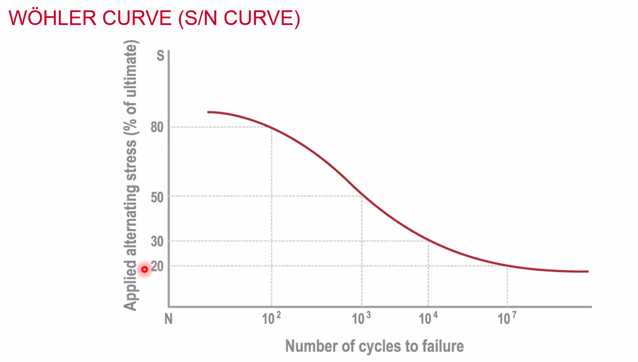
Ultimate Stress - fail point of a single application of a static load
- In flight
- loaded and unloaded many times
- below ultimate stress
- Cumulative stress
- weakening
- known as metal fatigue - think about opening a can and wobbling the opener
- fail as well below the ultimate stress level
High Cycle Fatigue - high cycle many small movements Low Cycle Fatigue - fewer, larger movements
Design Philosophies
- Fail Safe
- Parallel or multiple path loads
- redundancy of load bearing components
- Damage tolerant
- Safe Life - this will fail as X point, may be:
- Cycles
- Hours
- Landings
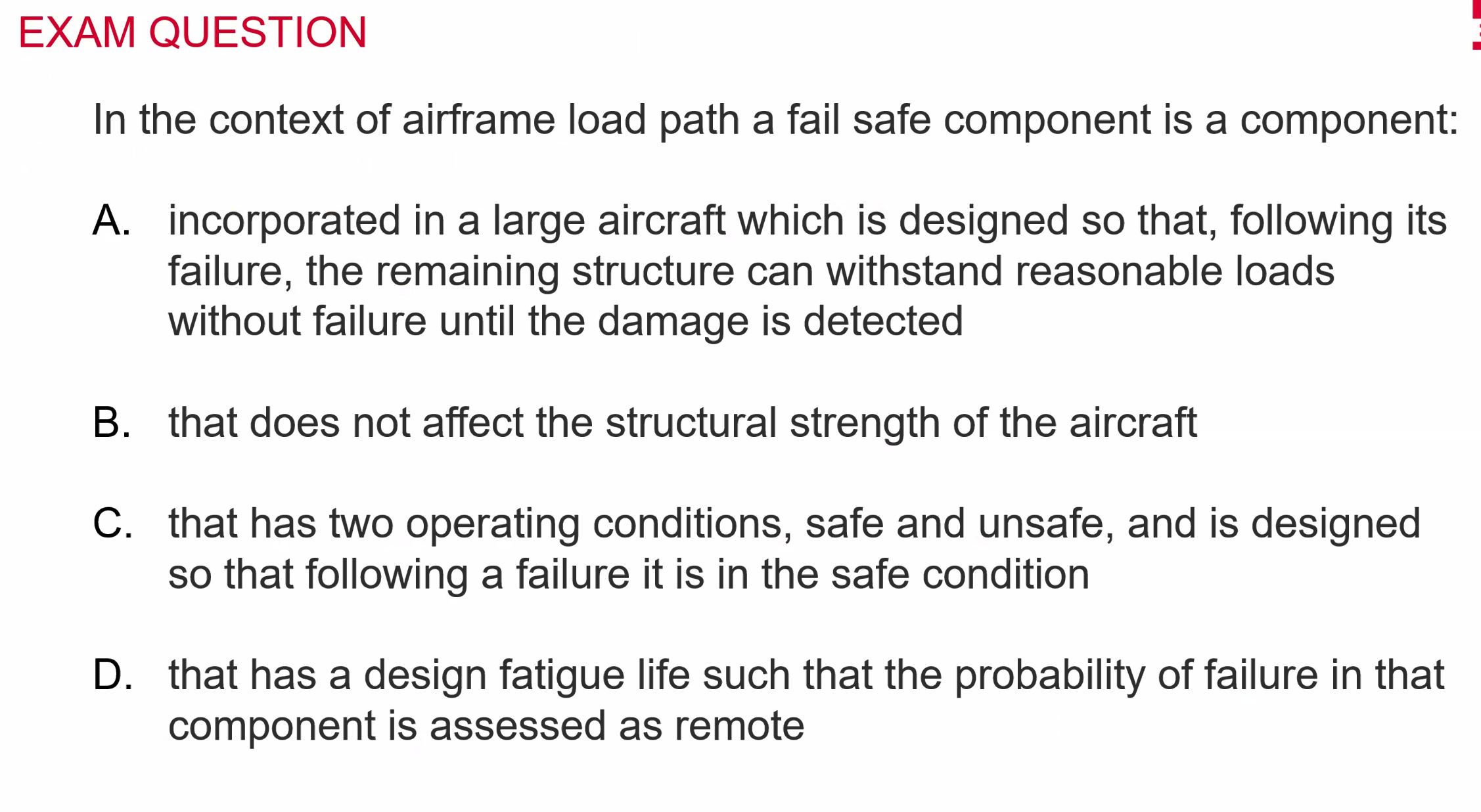
Answer: A
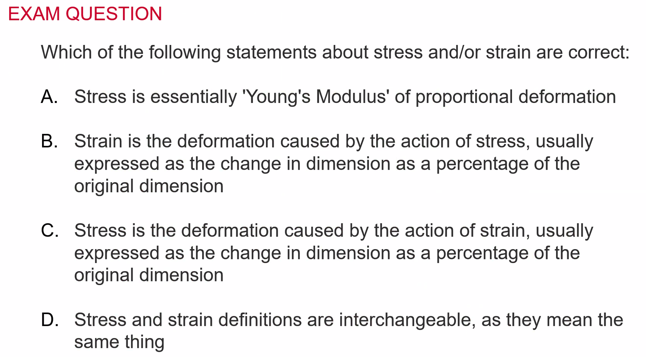 Answer: B
Certification Specifications
- EASA CS
- Flow from JAA CS
- Didn’t have legal ‘teeth’, they could create regulations but it was down to the national authorities to implement / enforce them
- Mirrored in the USA as FAA CS
- CS25 - Large Aeroplanes over 5700kg, more than 19 seats
- CS23 - Light aircraft
Materials
Ideal Properties
- Low density
- High strength
- High stiffness
- Corrosion Resistance
- Fatigue tolerant
- High operating temperature
- Ease of fabrication
- Low Cost
Types of material
- Aluminium
- Create alloys from it
- Create Alclad
- Magnesium Alloys
- Titanium Alloys
- Monel - great for heat
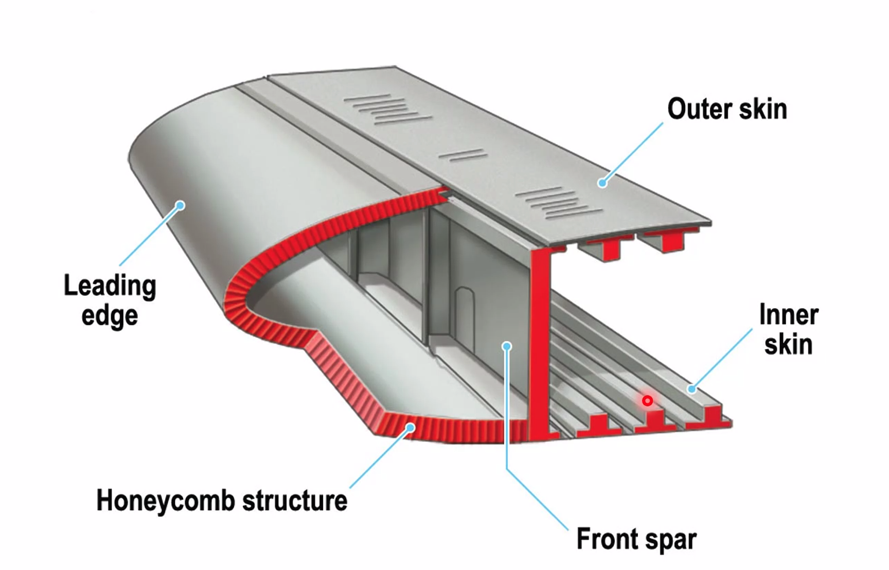
- Honeycomb
- Composites
Aluminium Alloys
- Duralumin - mostly aluminium, 3-4% copper has been added to make it stiffer with 0.5-1% manganese, 0.5-1.5 magnesium, traces, silicon, zinc, nickel, chromium, lead, Bismuth. First used in a Junkers J1 in 1917.
- Alclad - invented in 1927, Dural bonded with Aluminium and rolled together. Strong as mild steel but much lighter.
- Disadvantages - poor corrosion resistance but better than aluminium, lower operating temps but difficult to weld
- Advantages - Low density, High strength, high stiffness, fatigue tolerant, ease of fabrication, good thermal conductivity and low cost
Magnesium Alloys
- Less dense than aluminium
- Good at low operating temperatures
- but is susceptible to corrosion so frequency inspection required
- used in castings, gearboxes etc
Titanium
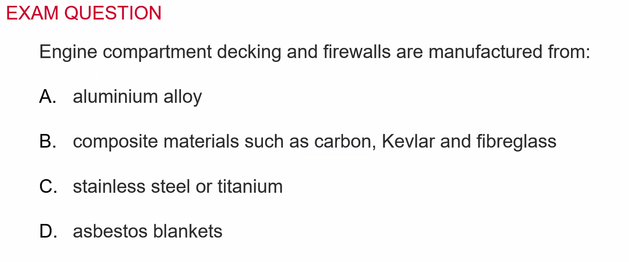
- mainly used in Firewalls / engine bays
- Titanium or Stainless steel
- Expensive, difficult to work with, very strong, can maintain up to 400C, Welded with electron beams
Monel
- Nickel / Copper Alloy
- Stronger than pure nickel
- Invented in 1901
- 3 times more expensive than carbon steel
- melting range 1300 - 1350C
- Many aerospace applications
- rivets
- wire
Honeycomb
- Epoxy bonded
- Honeycomb core - corrugated cardboard with metal or composite outer sheets
- Light but stiff
- Not tolerant of concentrated loads
Composites
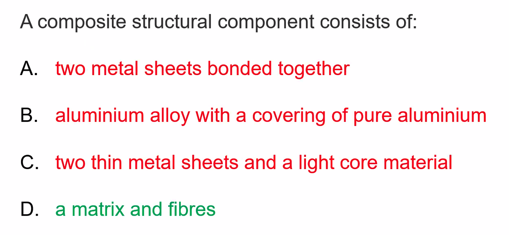
- Fibres with polymer resin matrix. Can be:
- Carbon
- Glass
- Kevlar (aramid)
- Random pattern, so same strength in all directions
- Laid in one direction? tailored direction strength. Able to be bended around a leading edge. Can also be weaved to make very strong.
- Pre-preg with an epoxy resin, just cut to shape, put in the mold and then cook it in an auto clave and you have a pre made solution
- ‘Soft Fail’ - detectable as fibres break.
Corrosion
Oxidation
- Dry corrosion
- reaction of a metal and environment without an electrolye Electrolytic
- Wet corrosion
- Impure water
- Other conductive liquid
- two dissimilar metals
- Effectively creates a battery - the annode (+) corrdes and the cathode (-) material added.
Stress Corrosion
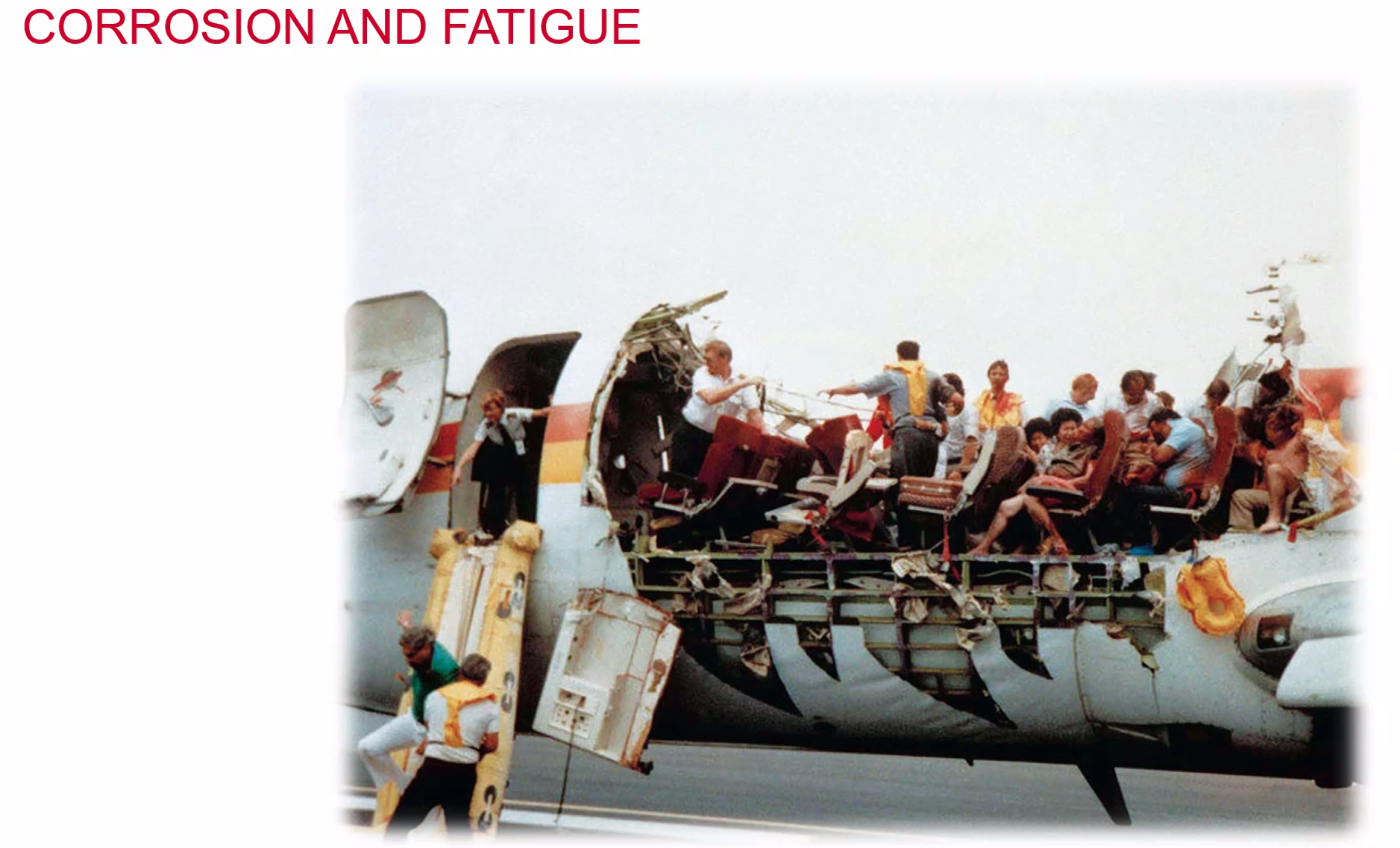
- interaction of corrosion and fatigue
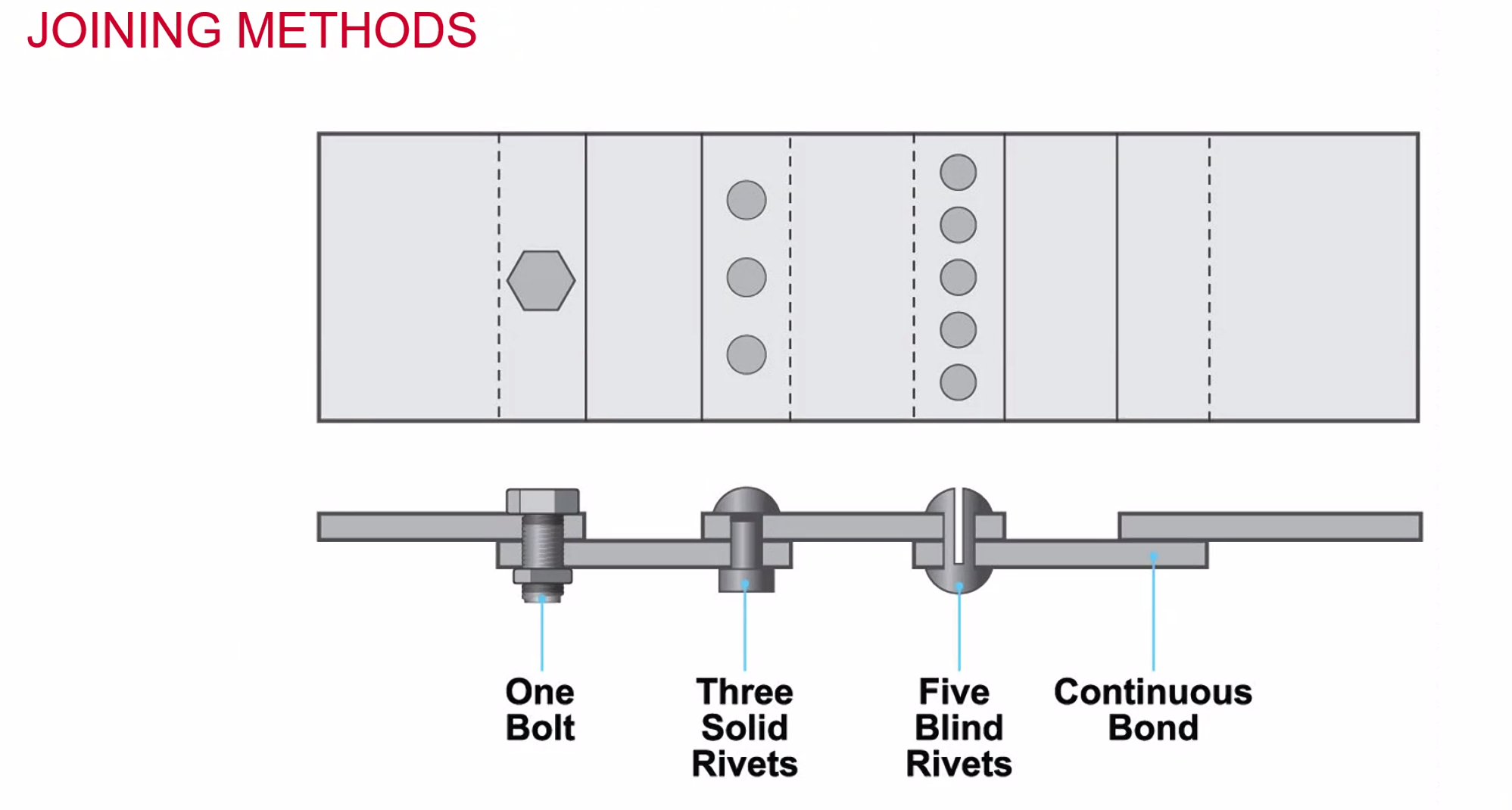
Joining Methods
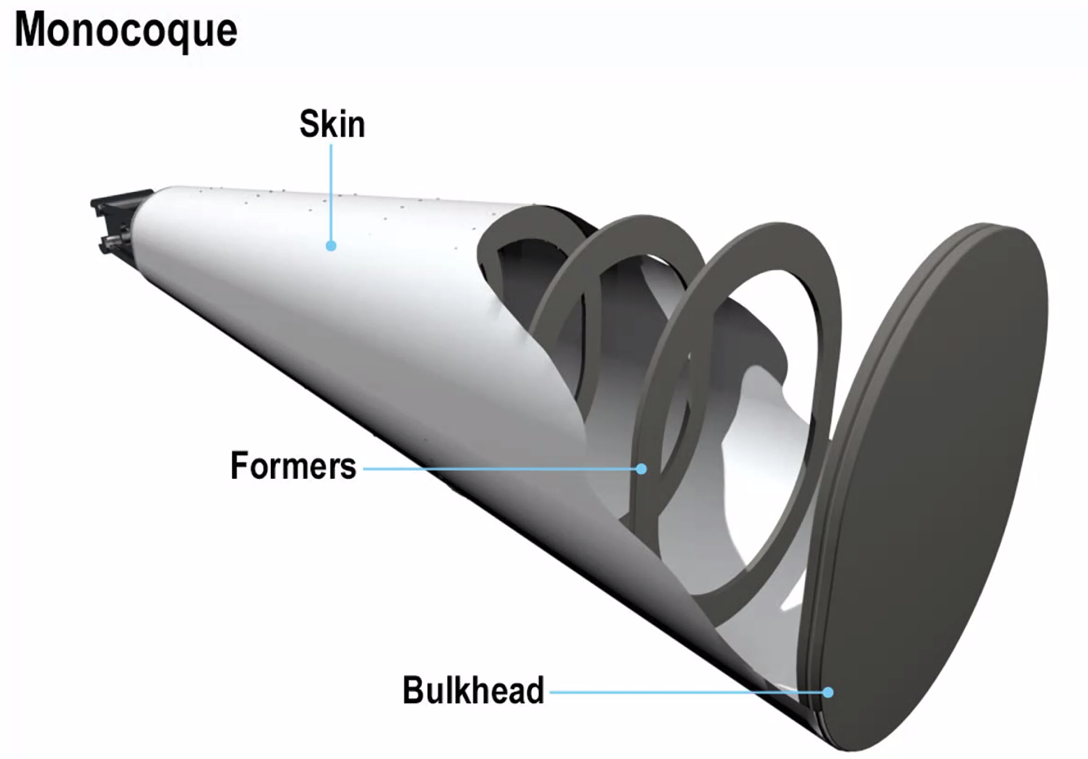
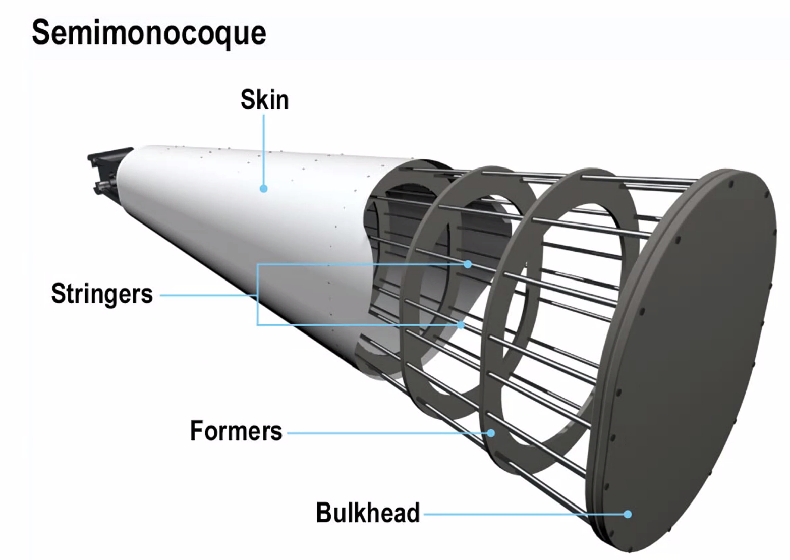
Aircraft Construction
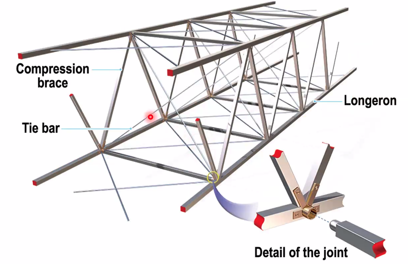
Box Airframe Construction
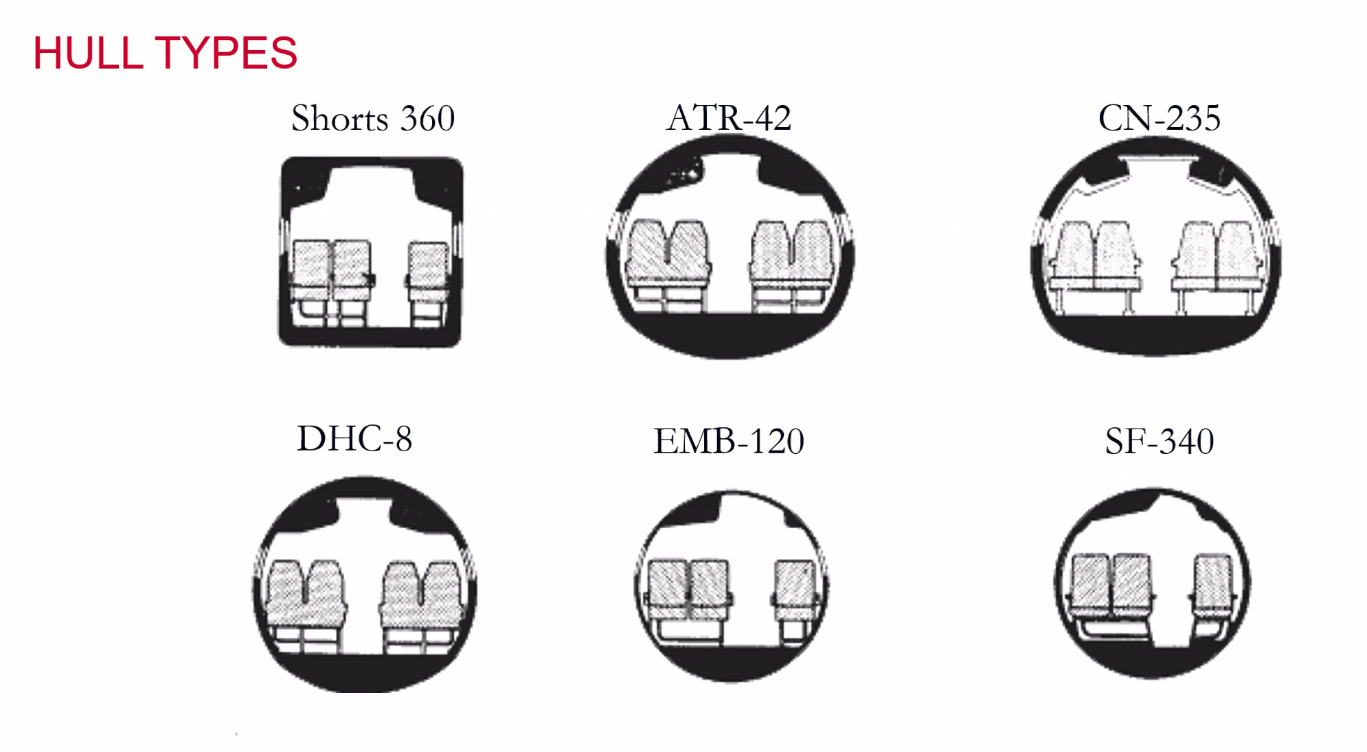
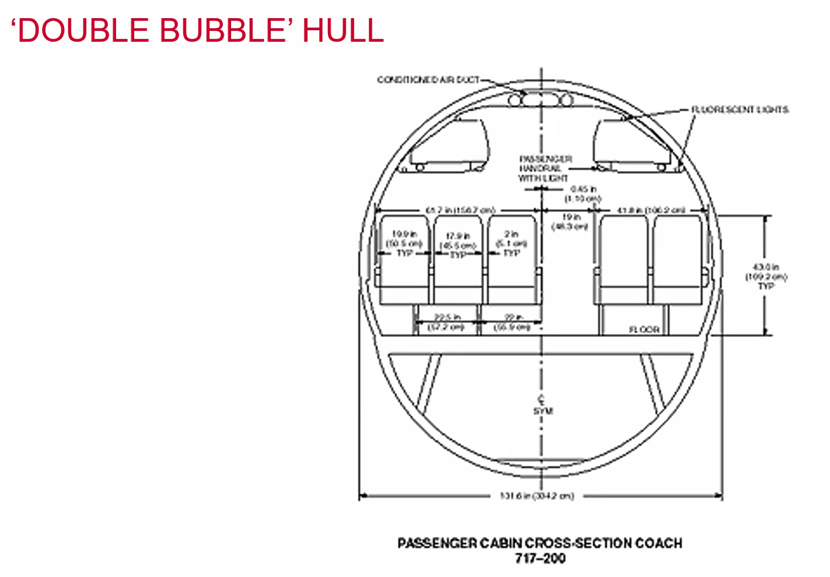
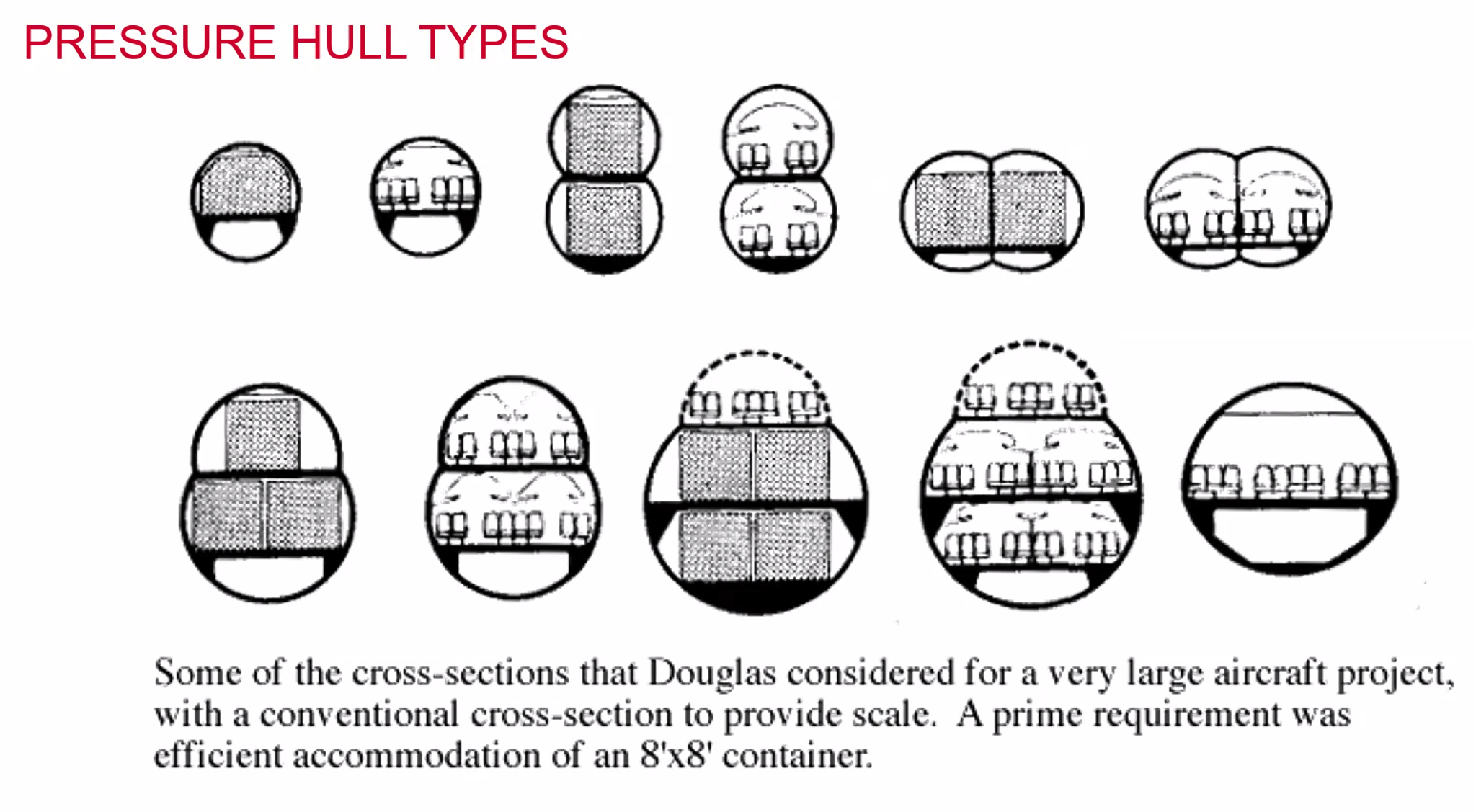
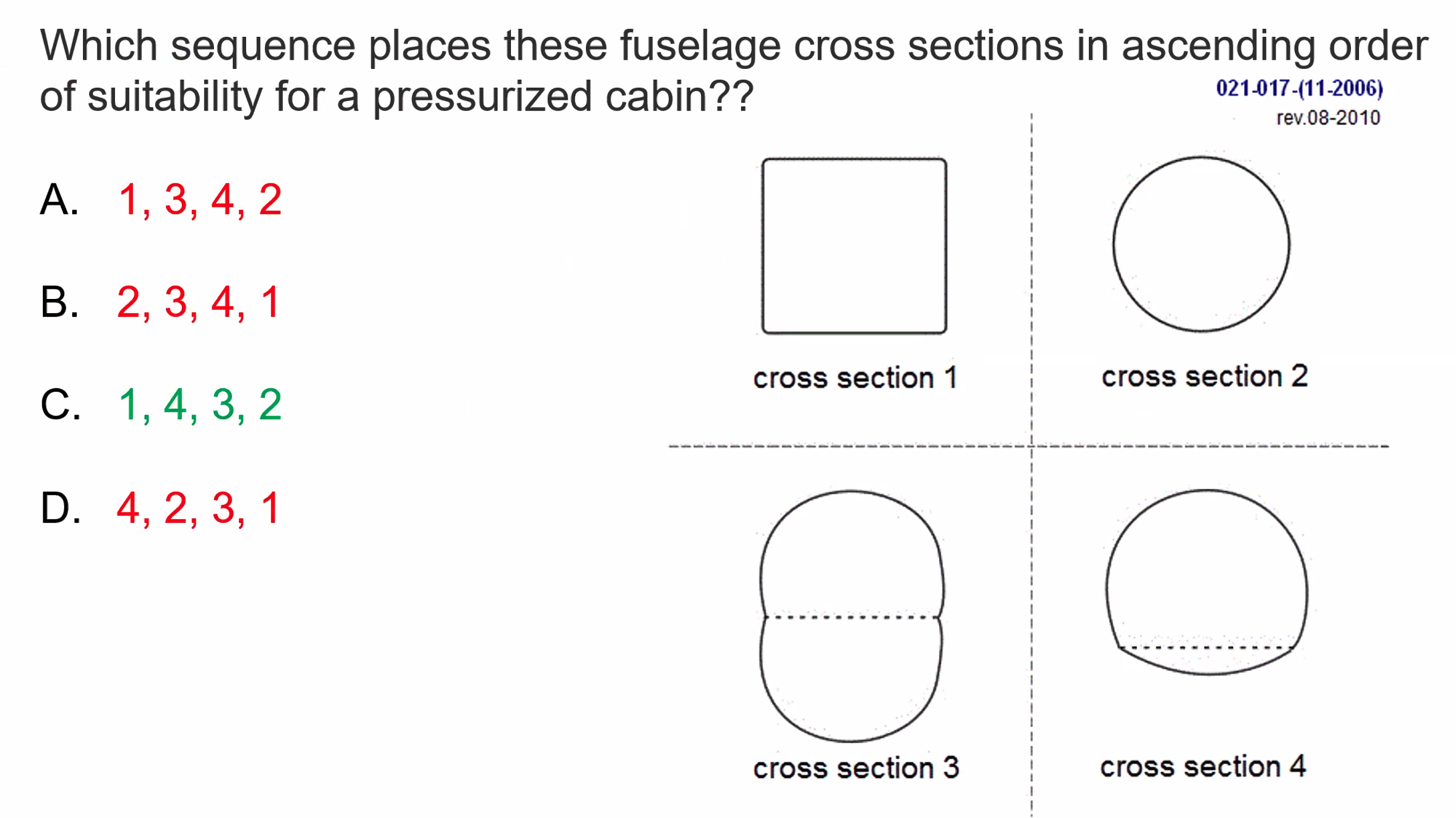
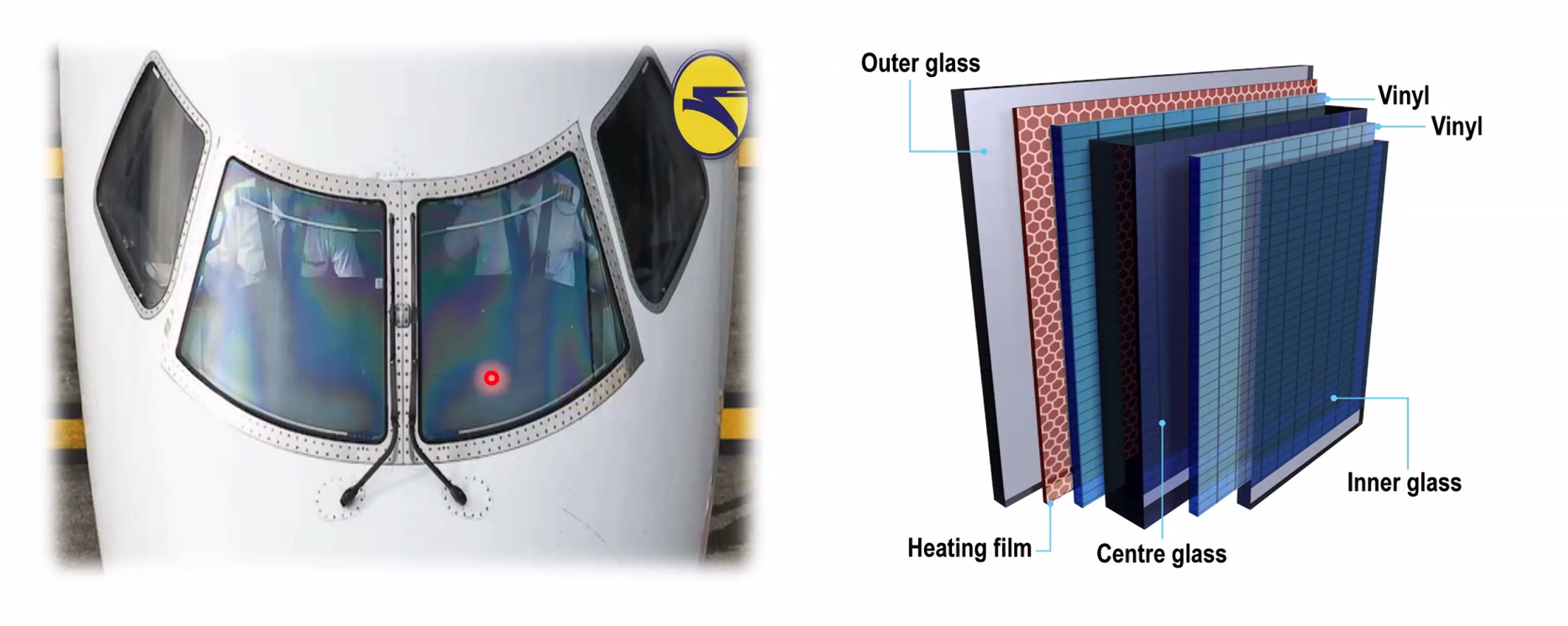
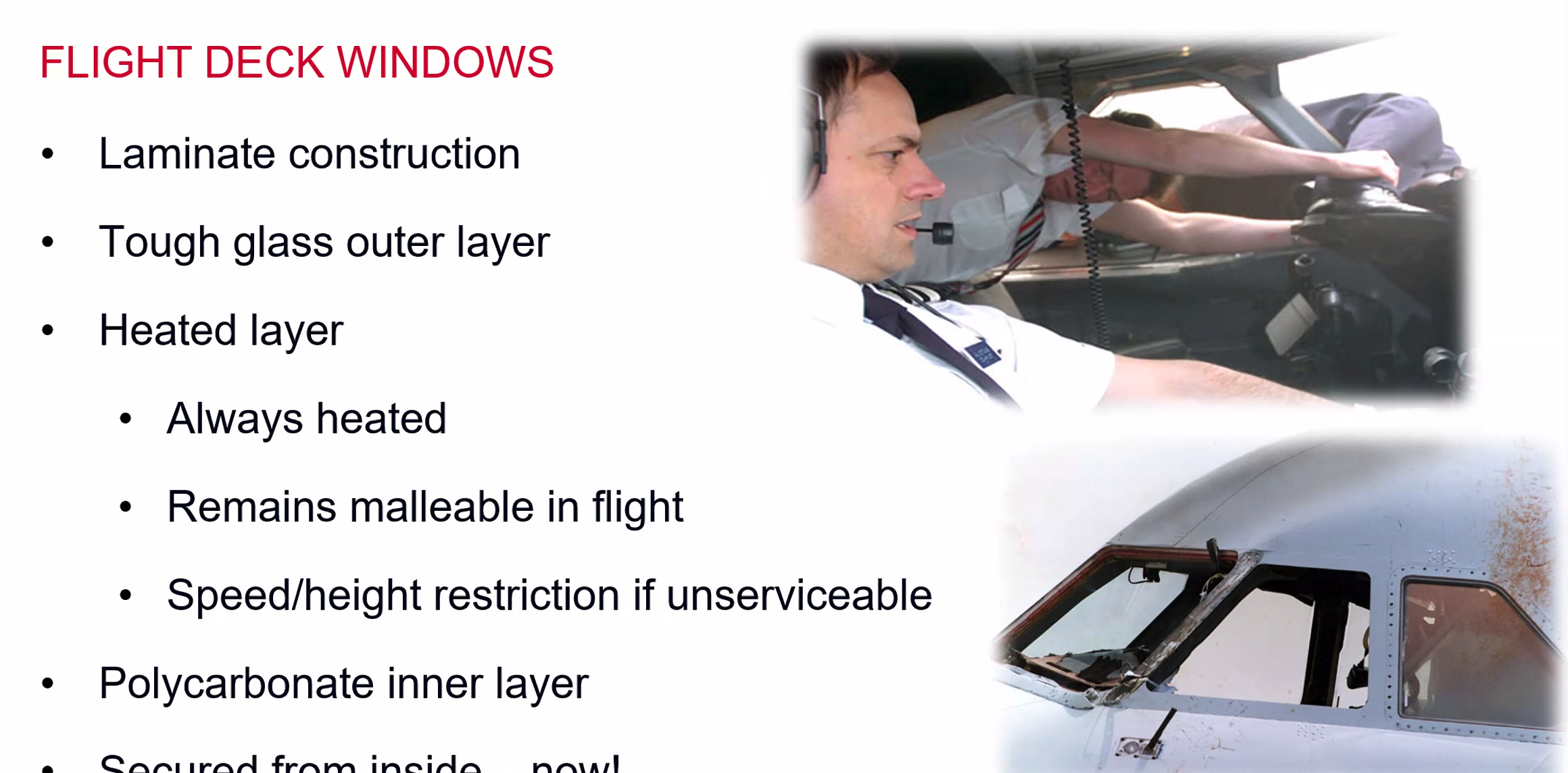
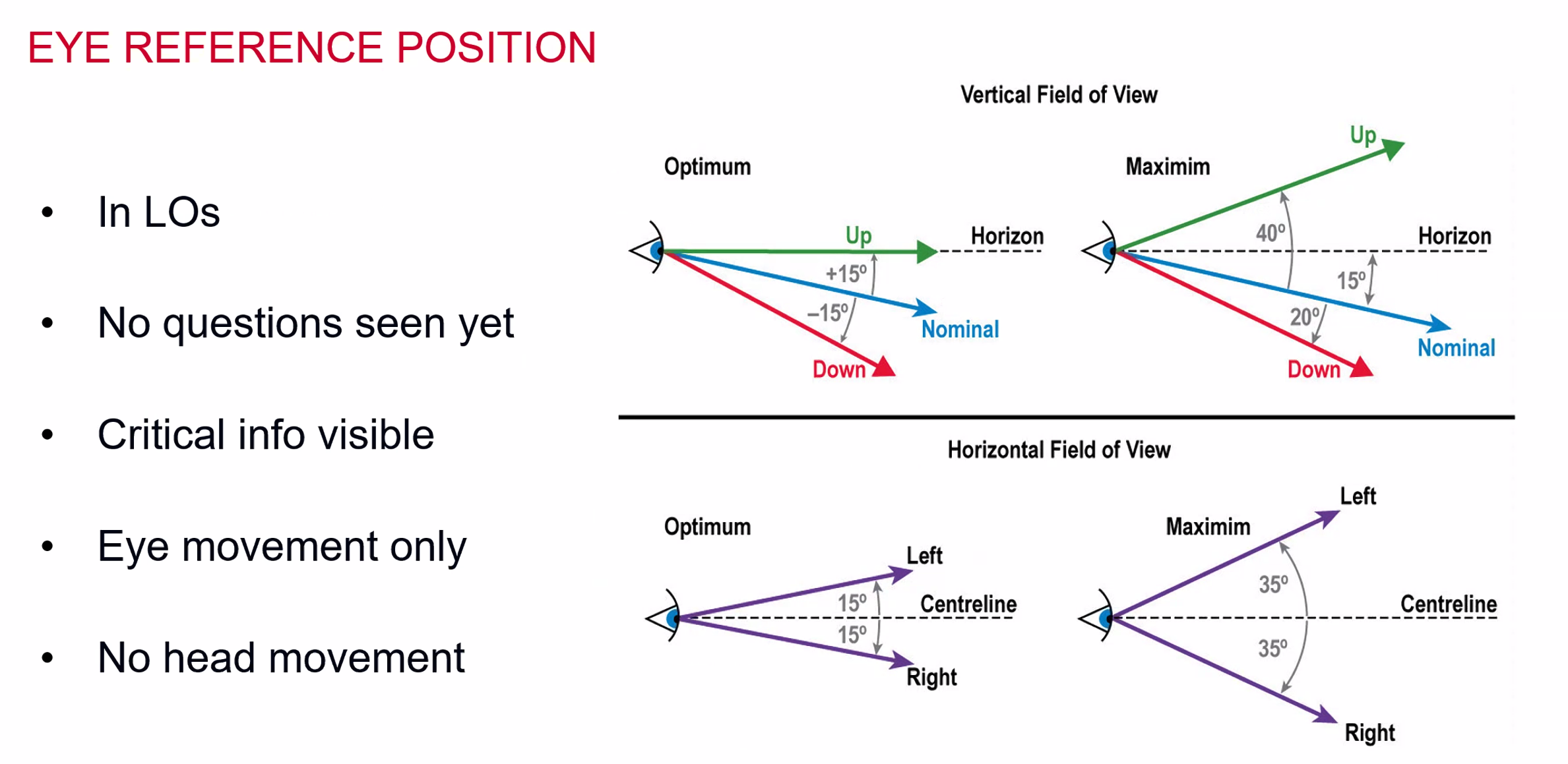
Flight Deck Windows
- designed to flex with the aeroplane
- glass is now a days mainly replaced with polycarbonate inner layer plastic (?)
- Tough glass outer layer
- Heated layer
- Always heated to remain malleable in flight
- speed/height restriction if unserviceable
- Secured from the inside
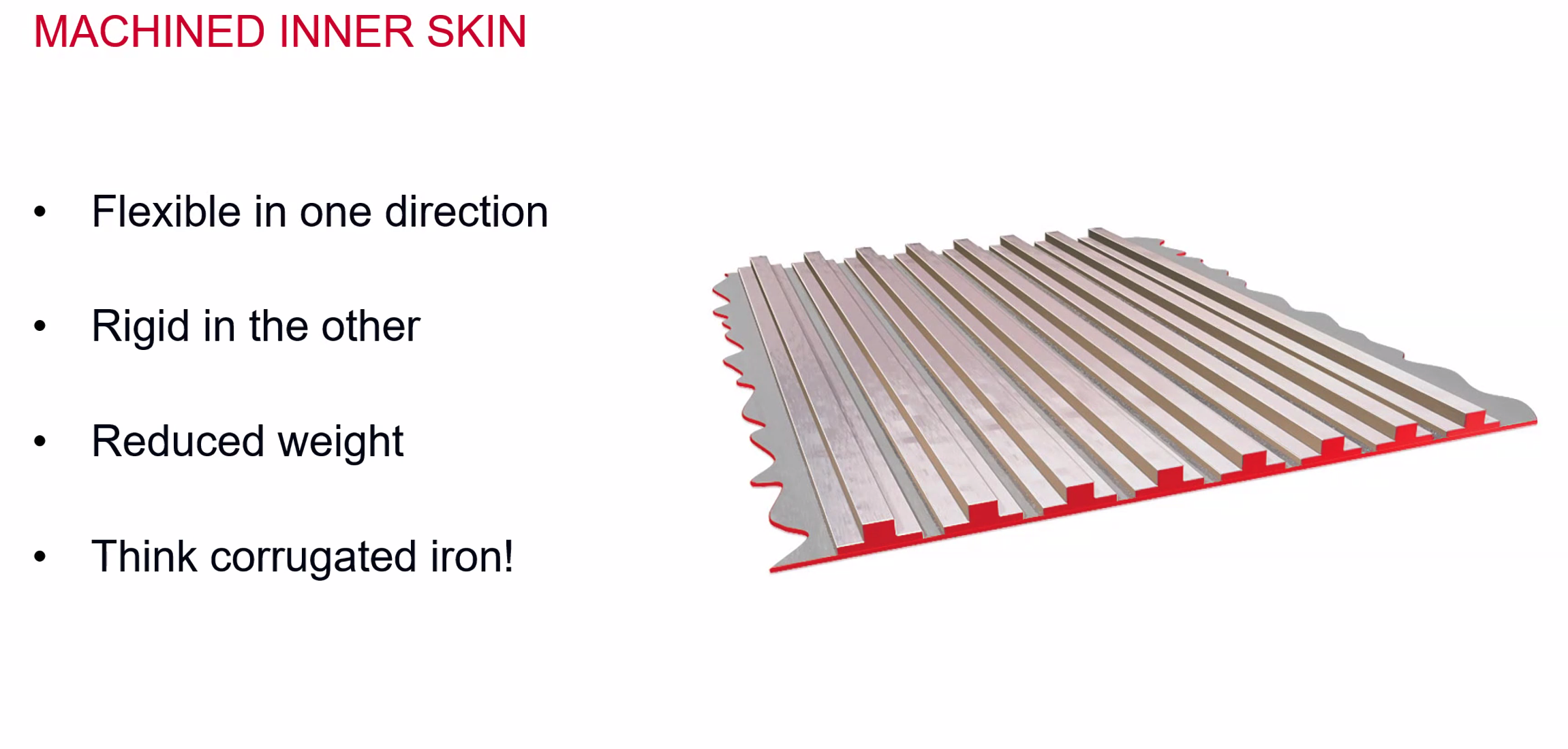
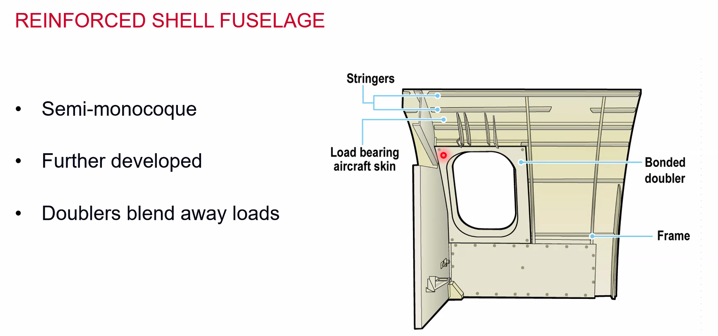
- Reduces stress concentration and makes it safer
Carbon Floor Panels
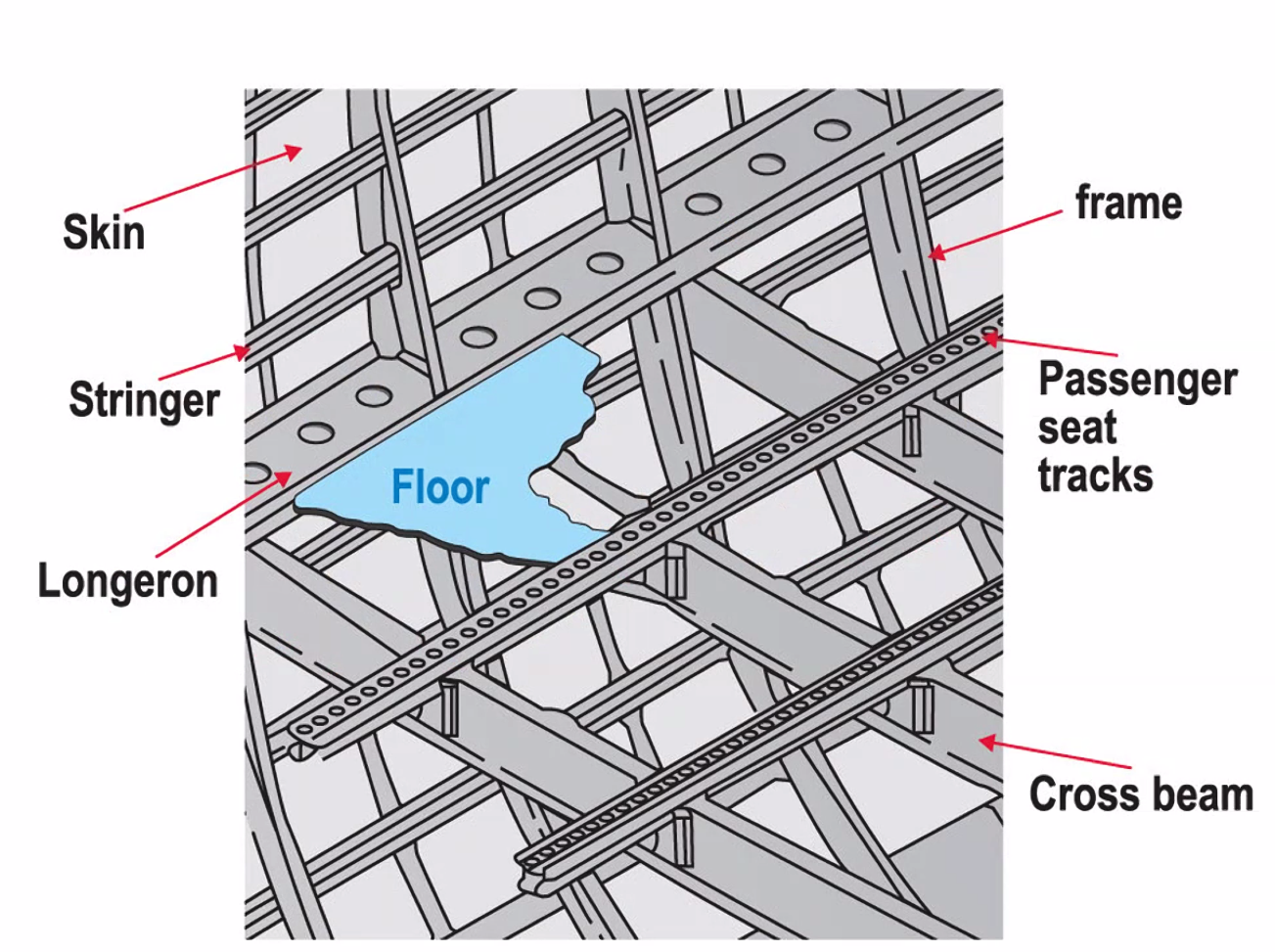
- Kevlar / AI / Nomex Sandwich
- Seat tracks on cross beams
- May be set into panel
- Cargo Floor - aluminium panels
- Plywood over panels
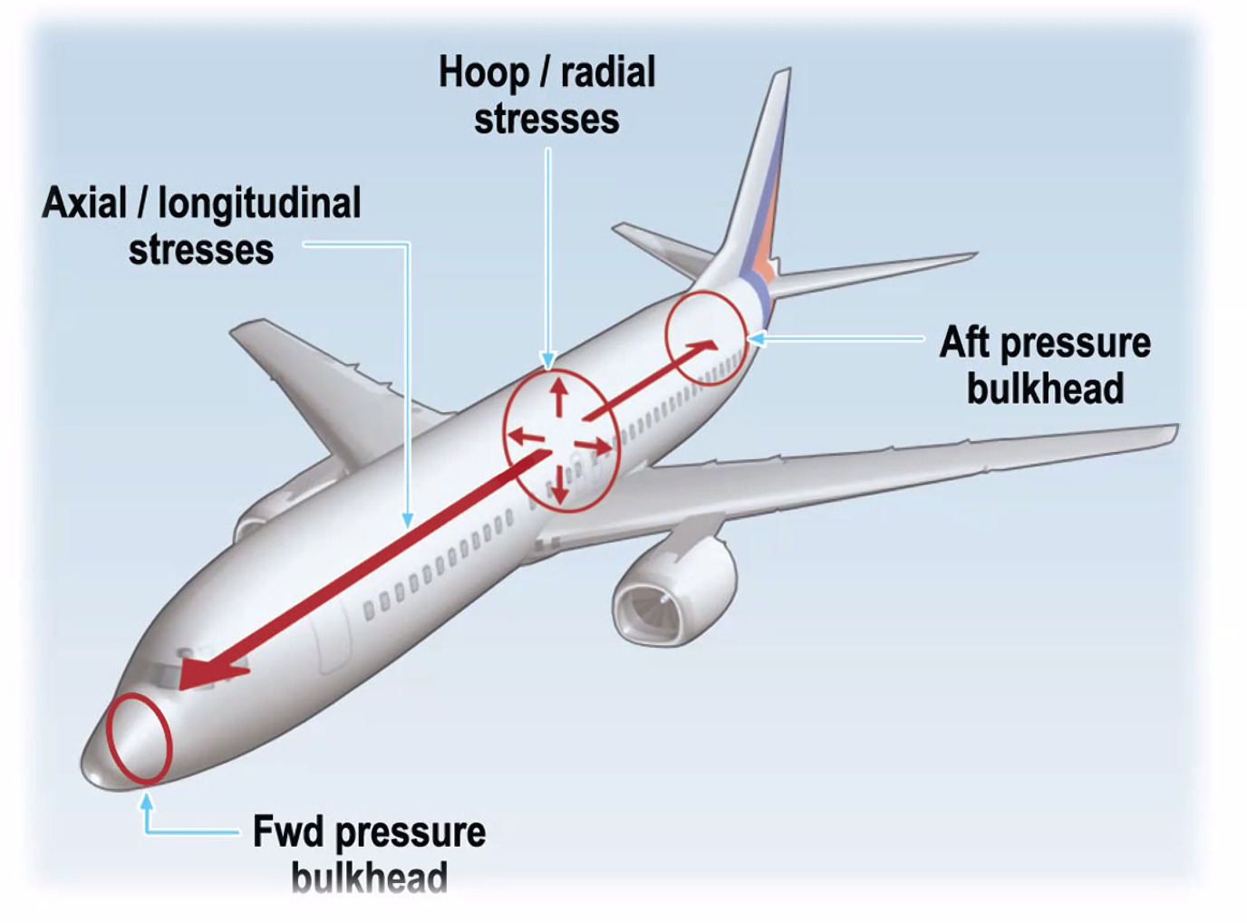
Pressurisation Loads
- Occurs once per flights
- not flight time critical - but the action of pressurising the aircraft
- Short haul will require a stronger construction due to more cycles than long haul aircraft
Doors
- Are of a plug type design, so that the pressurisation forces the door outward.
Wings
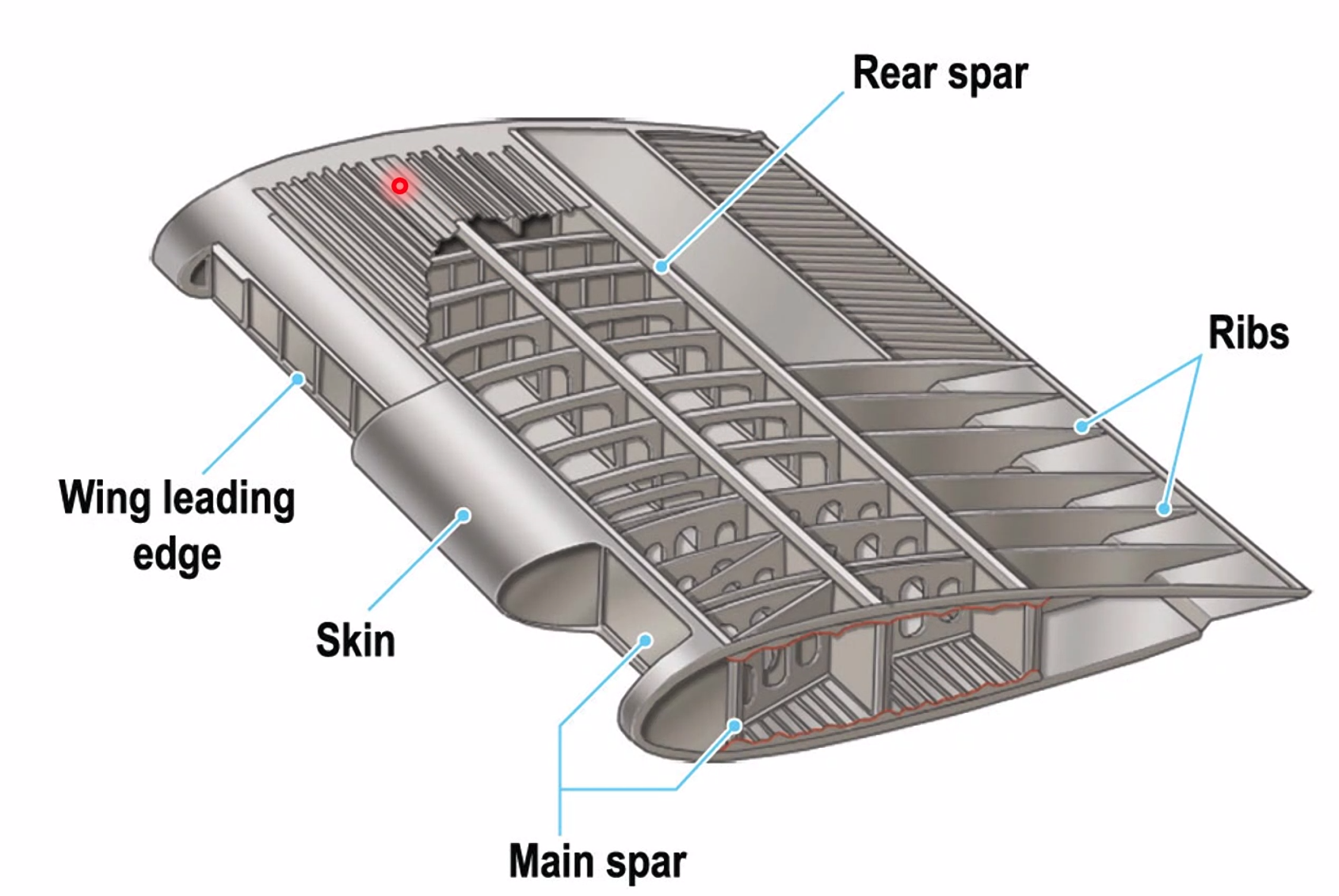
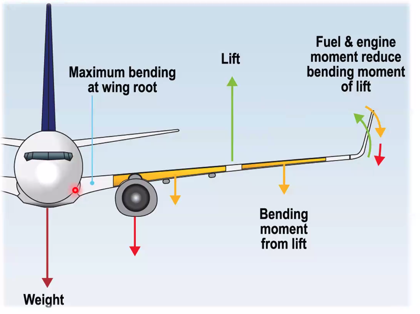
Wing Bending Relief - most of the bending will happen at the wing root. Needs to be offset by adding fuel into the extremities of the wing to reduce the stress at the wing root. Fuel is taken from the center tanks first, then the inboard tanks and then the outboard tanks but by the time you get to the outboard tanks the stress on the root will be much less.
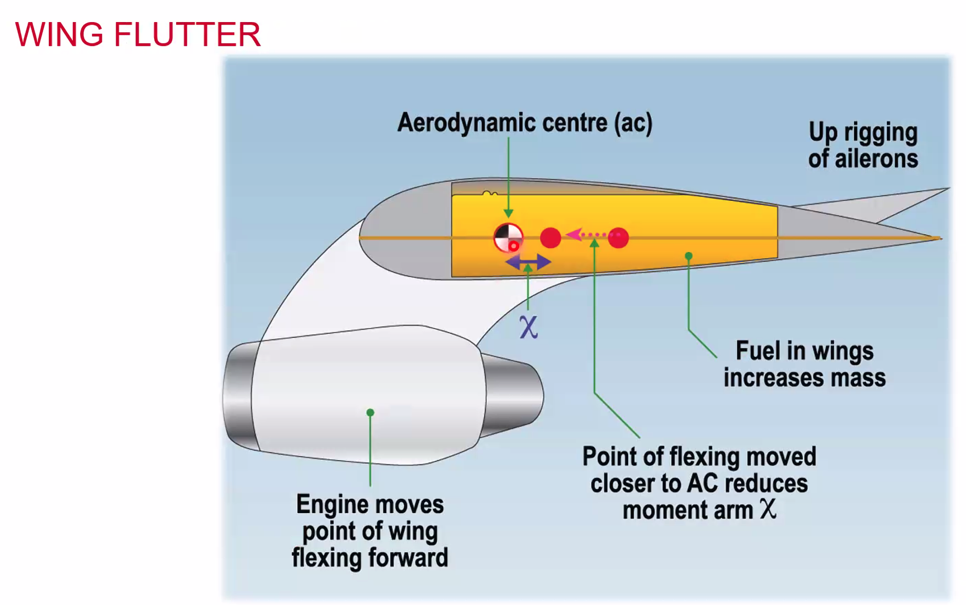
Flutter - vibration that can shake the aircraft apart - can lose a wing. Wing Flutter - Fuel in the wings increases the mass and so stability.
T-Tails - by putting the fin at the top of the rudder you increase the airflow and make it more effective during normal flight. HOWEVER, in a stall, the angle of the wings to the tailplane reduce the amount of smooth air hitting the tailplane and mean the (already smaller) tailplane has less drive / control… causing a deep, unrecoverable stall.
Maintenance
- Hard Time - replaced after a set amount of
- hours
- cycles
- operations
- On condition
- monitoring of critical parameters
- replacement of parts if a limit value is exceed
Hydraulics
Hydraulic Theory
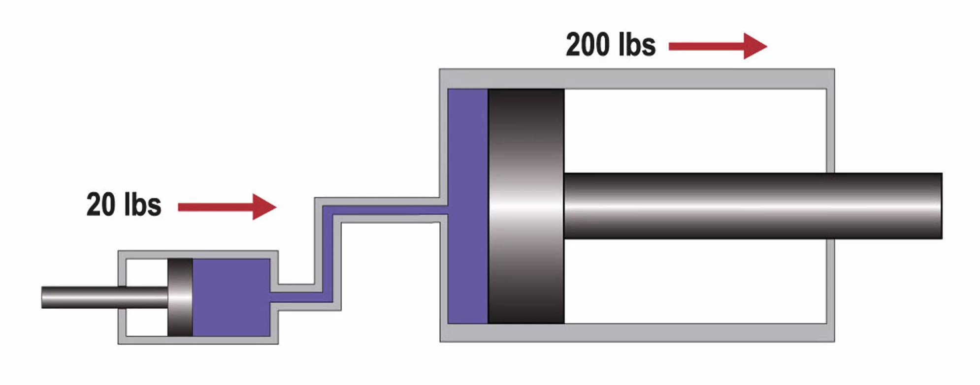
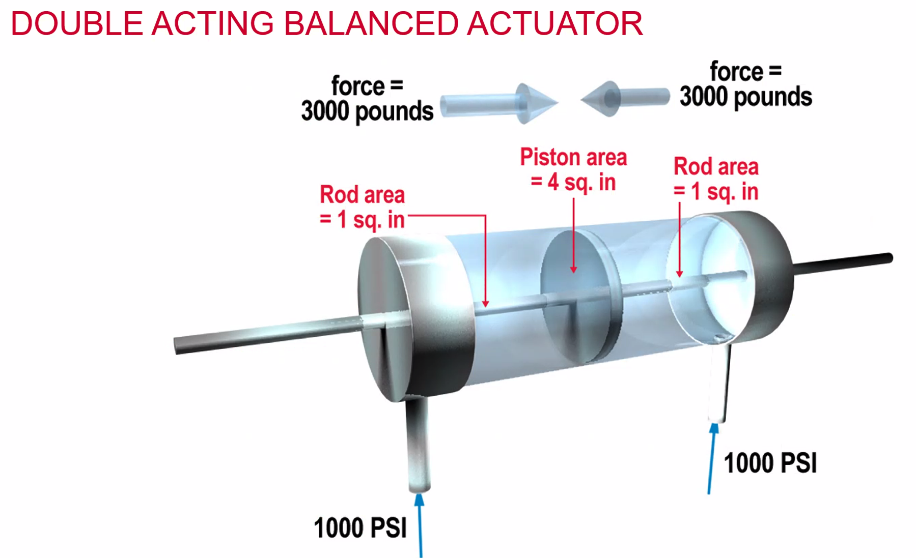
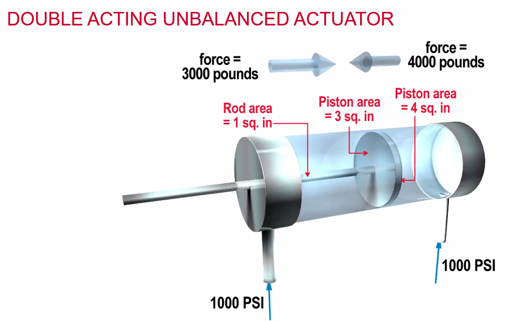
Pressure exerted is raised evenly throughout the container at right angles to the container. Hydraulics are a force multiplier. A small force can create a large movement.
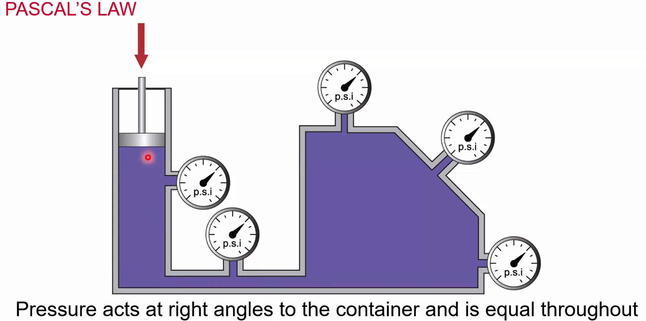
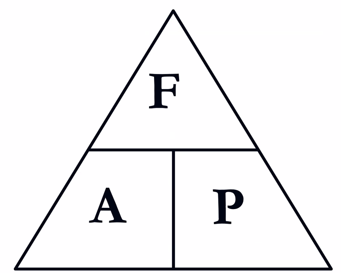
Force = Area x Pressure
Force multiplier - a small movement / input can create a large output / movement. The little piston is moved a long way to move the larger piston a small way.
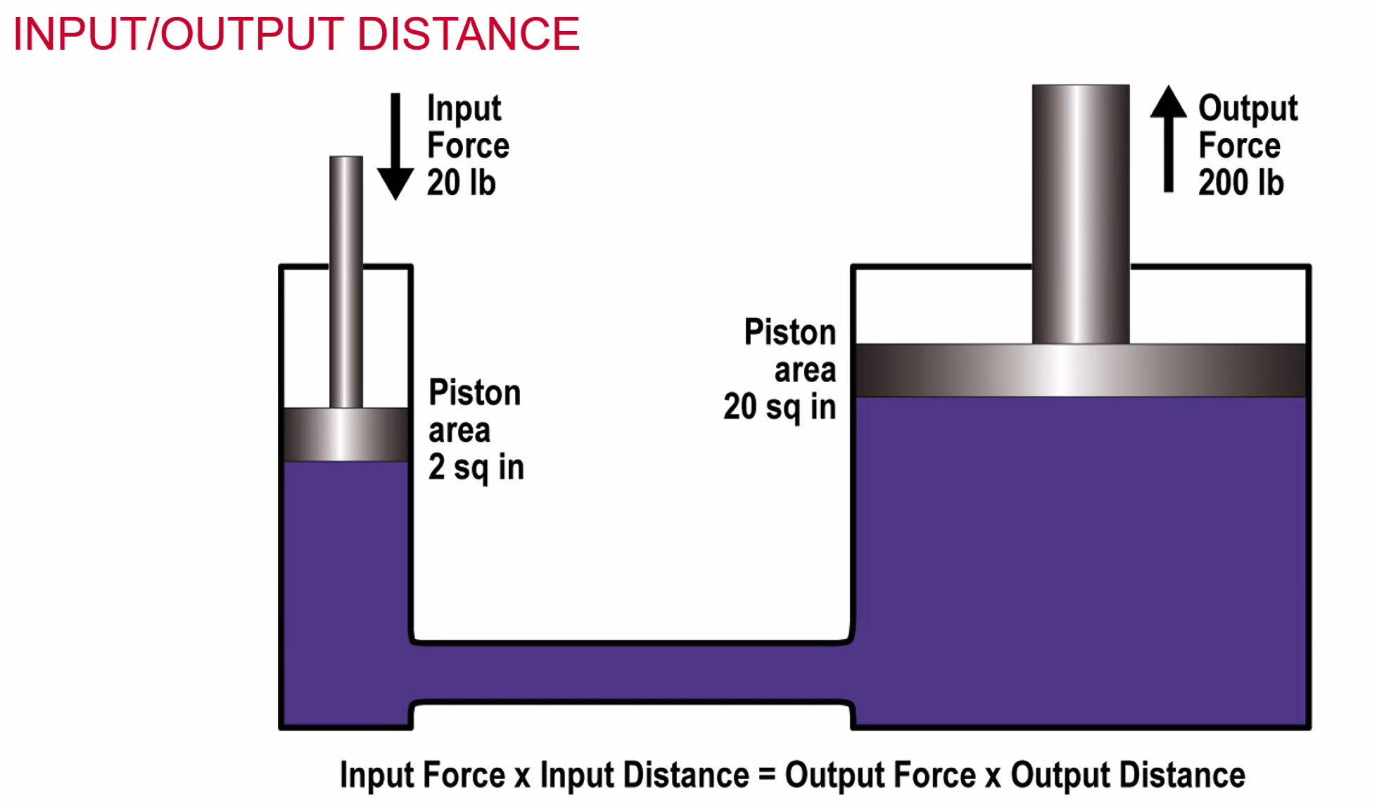
Input Force x Input Distance = Output Force x Output Distance
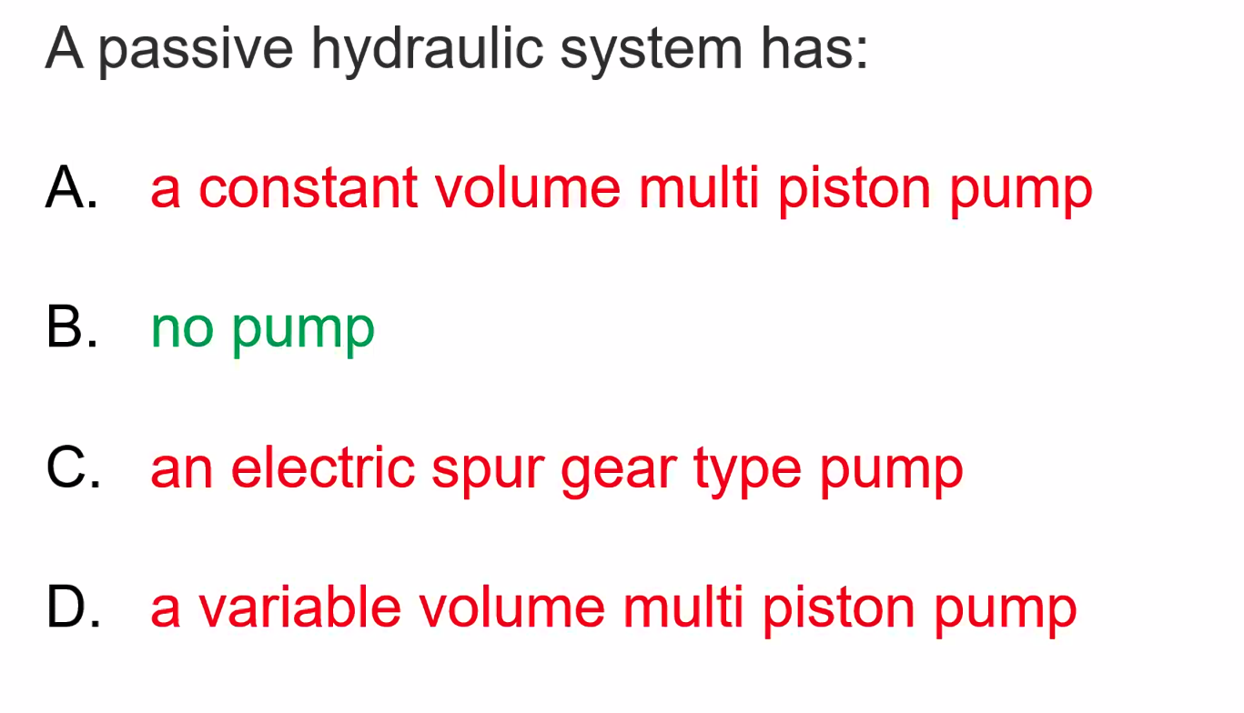
Passive Hydraulic System
man powered - example can be the brakes in a PA28/C172. The Parking Brake Valve acts as a non return valve once activated - stagnates the hydraulic system.
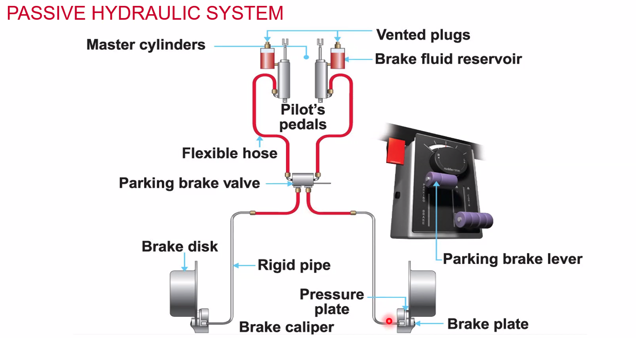
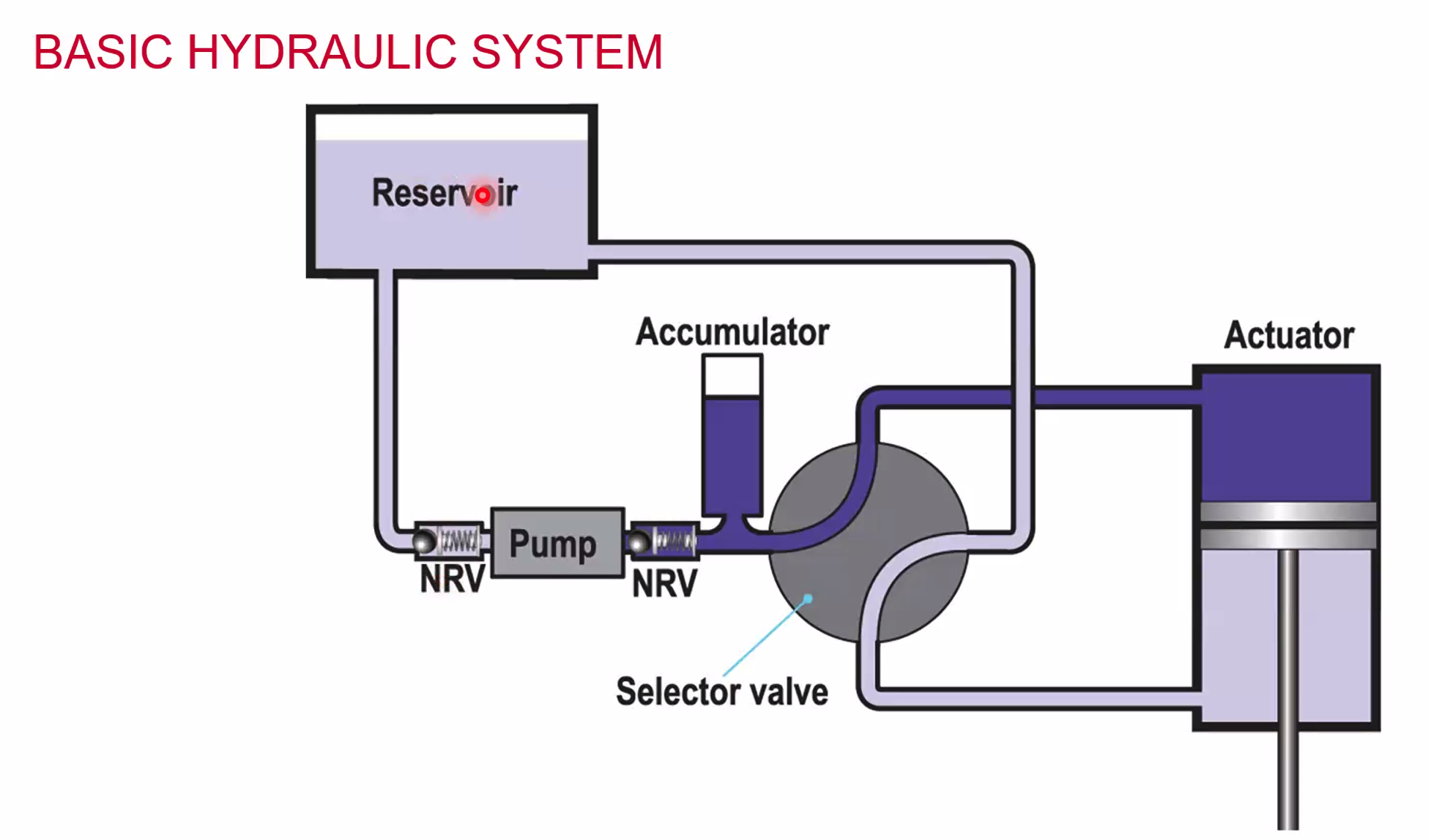 A very simple one actuator hydraulic system.
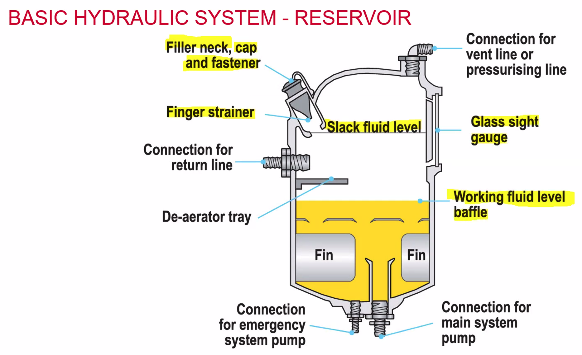
- Inside the reservoir there are baffles to stop the fluid from sloshing around.
- Fins help to dissipate heat. Provide a surface area for the fluid to impart it’s heat upon.
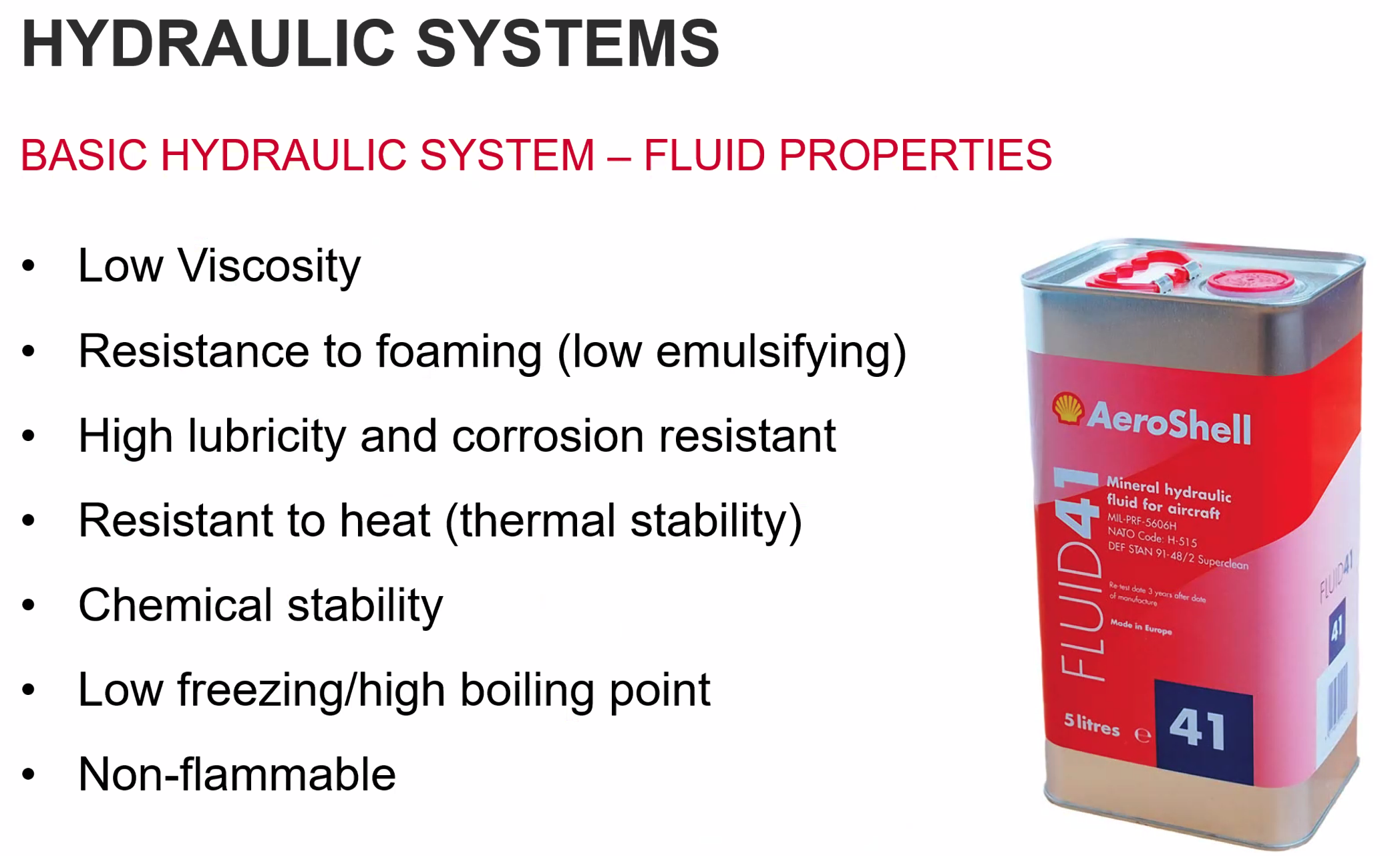
- Mineral Based (DTD 585)
- Dyed red
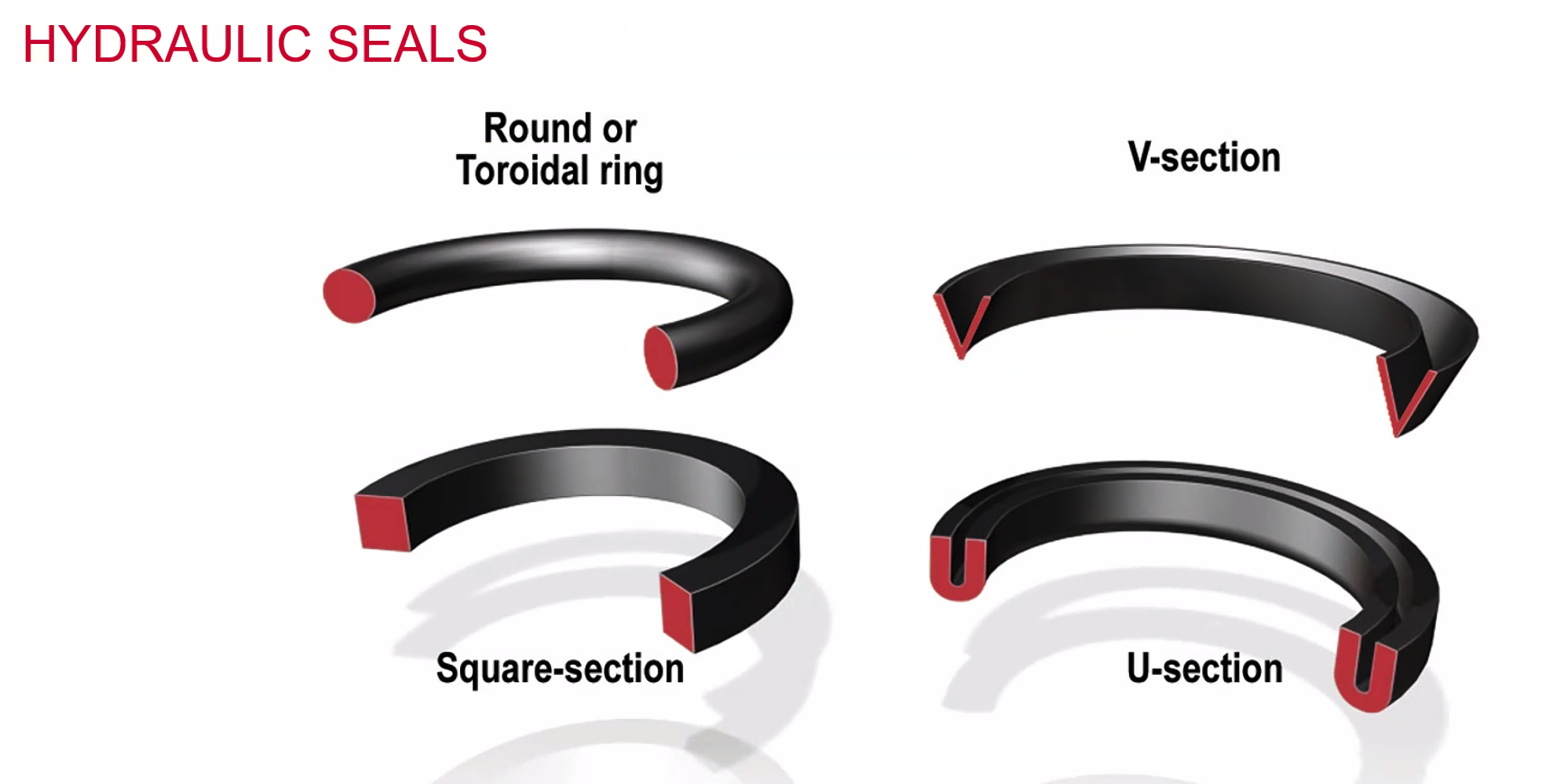
- Uses synthetic rubber seals
- Synthetic (Phosphate Ester)
- Skydrol
- Dyed purple
- Butyl rubber, ethylene
Modern aeroplanes systems are synthetic. Considered non-flammable.
Most helicopters use mineral. All types are irritant to eyes and skin. Types must not be mixed.
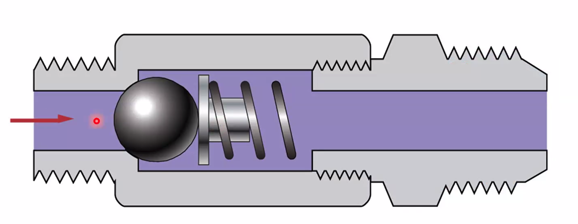
Non Return Valve
datum spring sets the cracking pressure - the pressure which will allow fluid to continue its path. To prevent mis-implementation they are stamped with an arrow to show the direction.
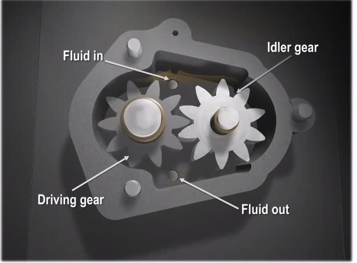
Spur Gear Pump
Consists of a driving gear and an idle gear. Only the driving gear moves. Driving gear moves anti-clockwise and adds an increasing amount of fluid to provide the pressure.
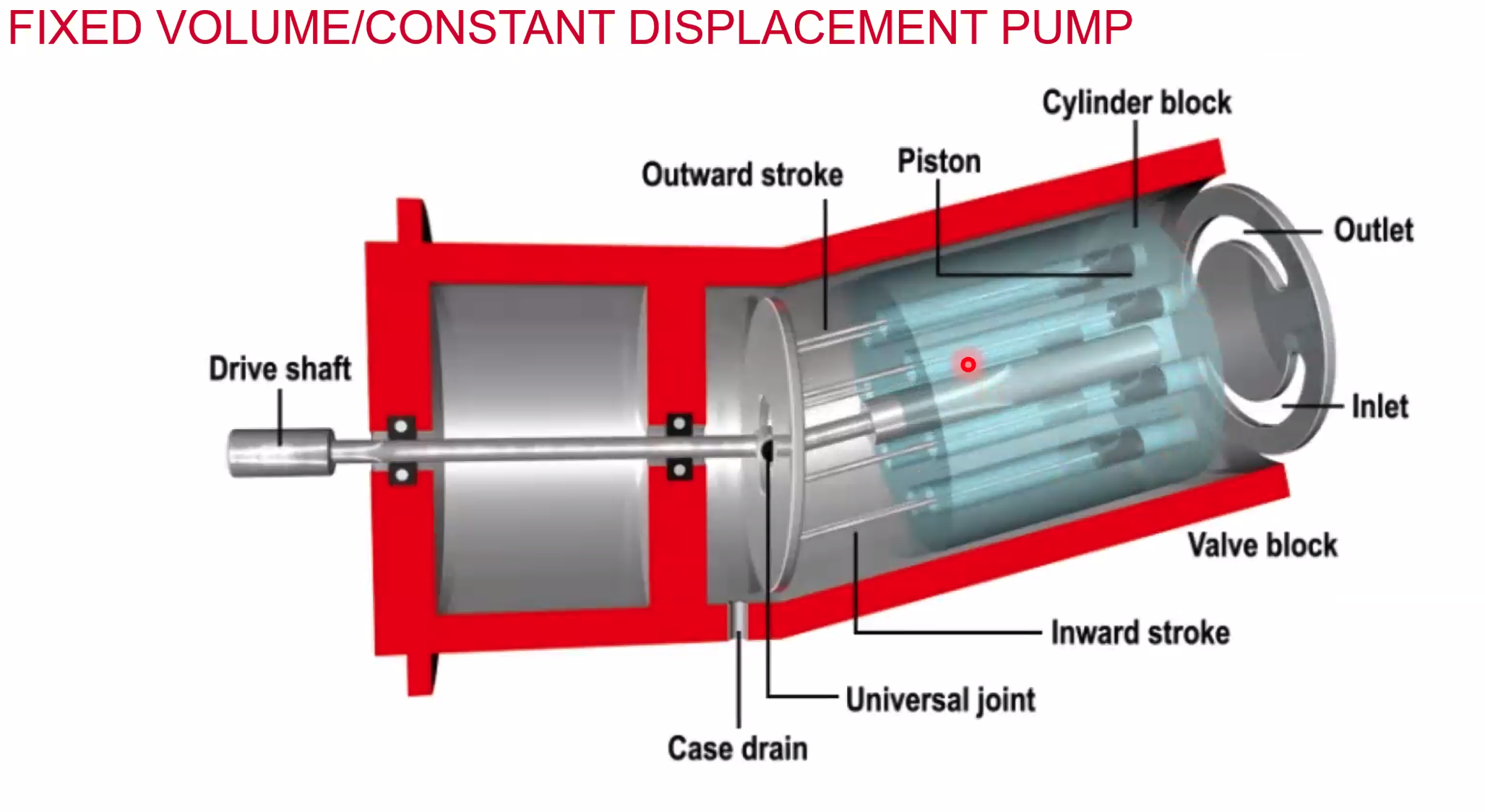
Fixed Volume Constant Displacement Pump
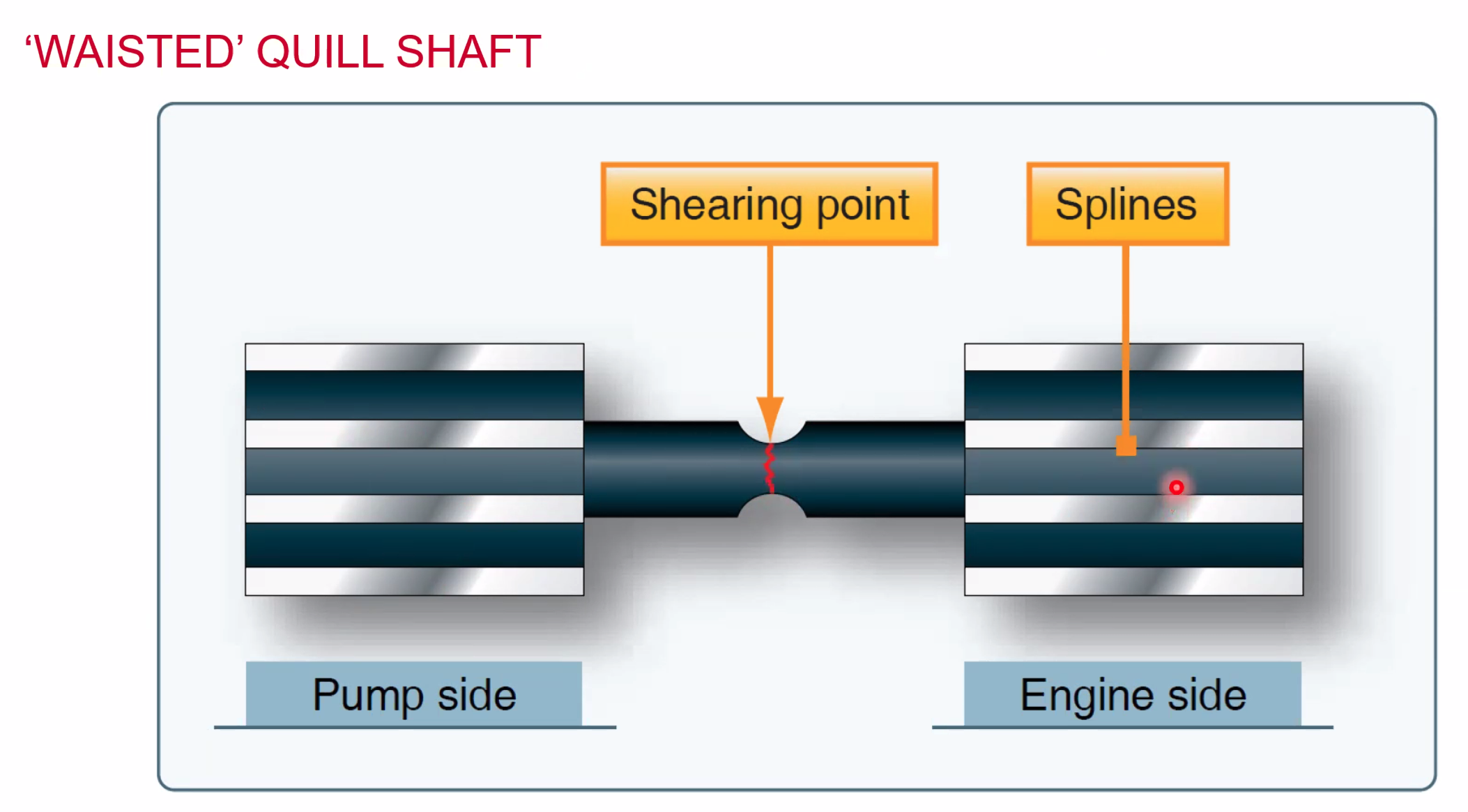
Not all of the fluid makes it to the outlet, some of it recirculates to lubricate the system until is goes to the Case drain at the bottom.
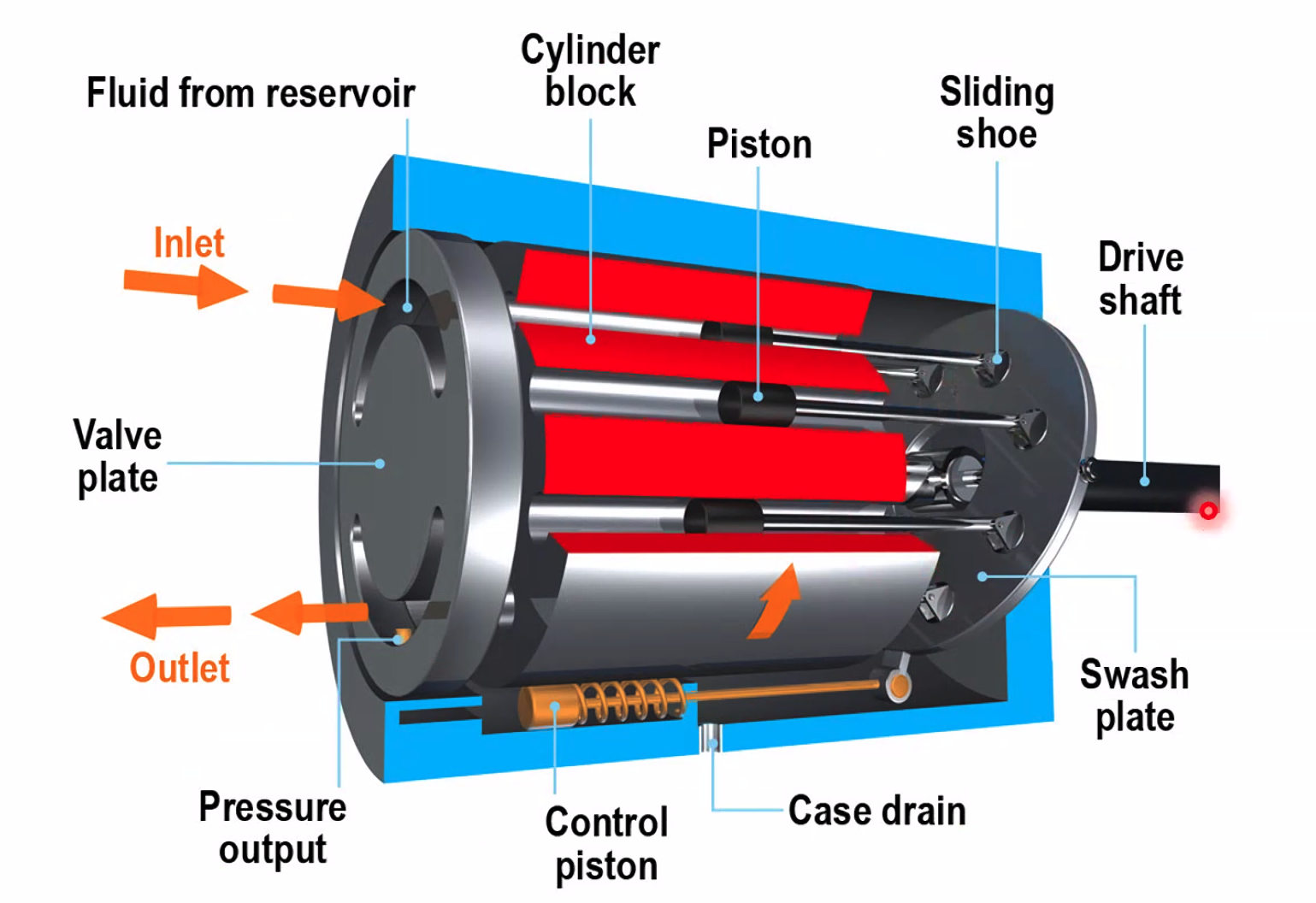
The control piston allows this to self-regulate its pressure. Too much pressure? Control piston is moved back and then forces the swash plate to a neutral position.
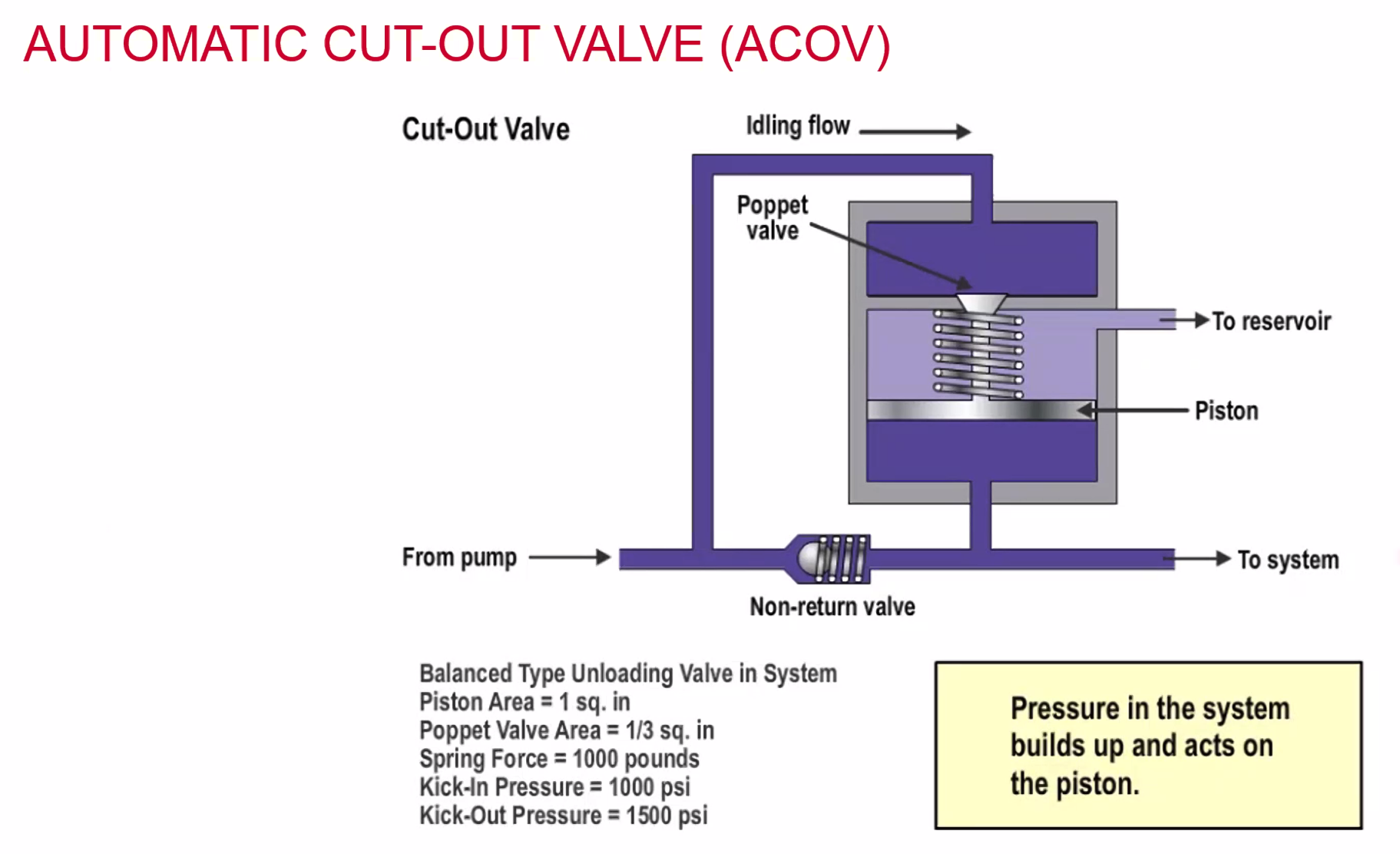
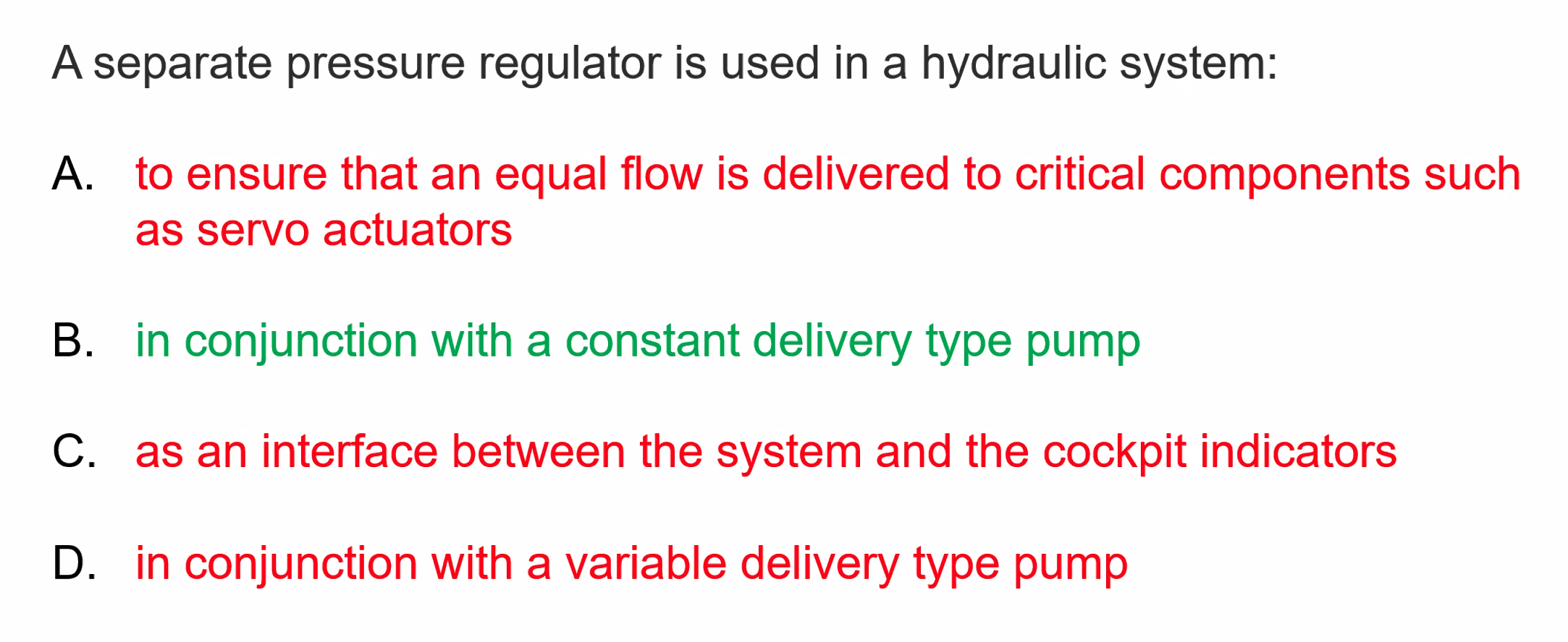
System works great but can cause hydraulic hammering which is where the pressure regulator will consistently smack against the poppet valve whilst trying to regulate pressure
Pressure Relief Valve
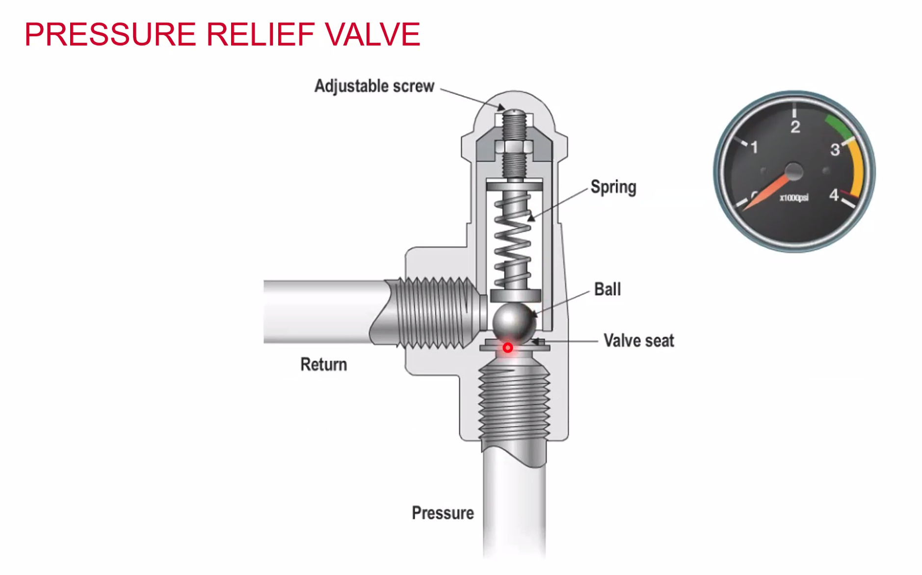
If these are able to take care of the full pressure they are called FFV. Full Pressure Relief Valves
Accumulators
- Store fluid under pressure (energy)
- Provide limited supply of pressure in an emergency
- Dampen out pressure fluctuations
- Allow for thermal expansion
- Cater for small internal leaks
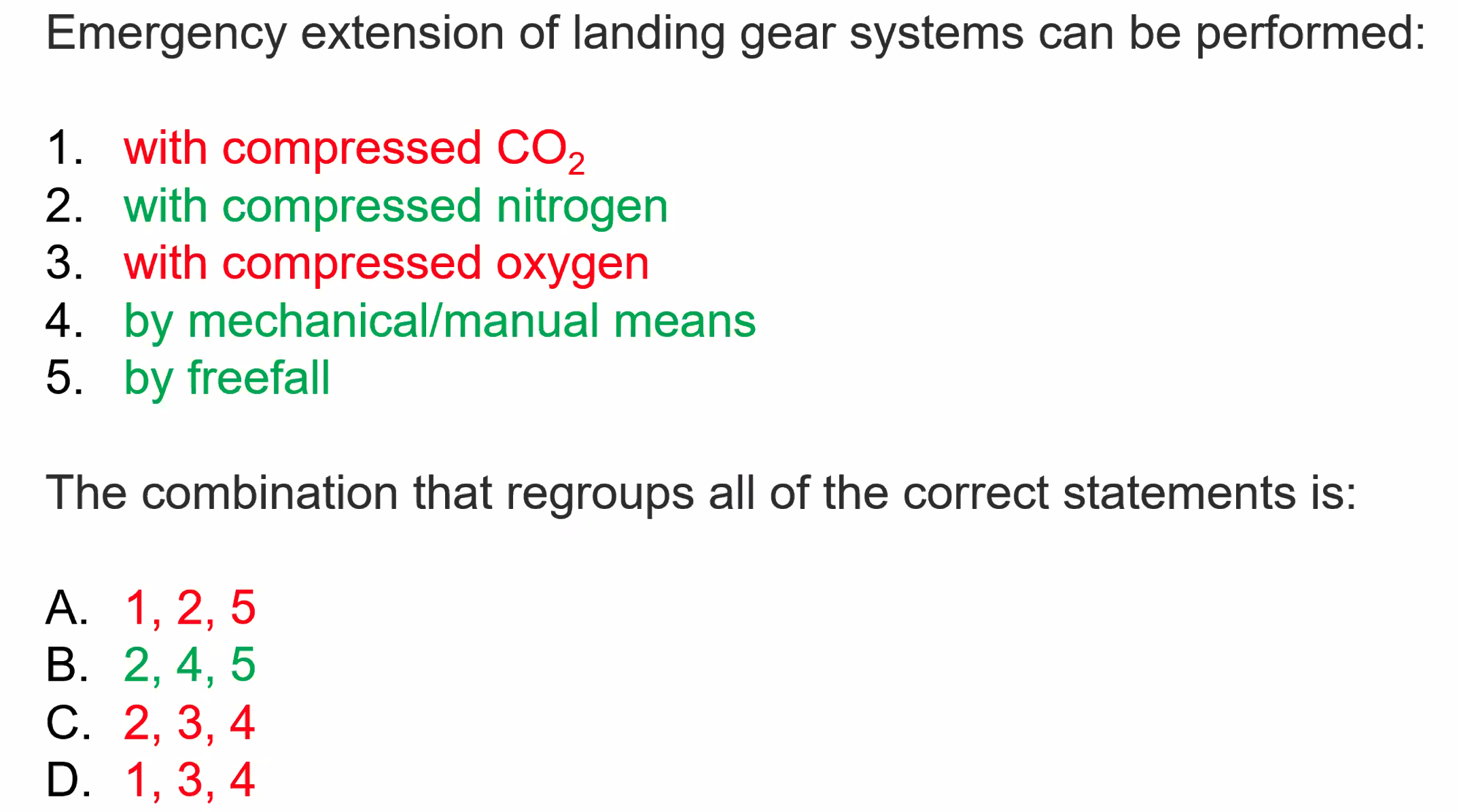
- A dedicated accumulator may be used to lower the landing gear.
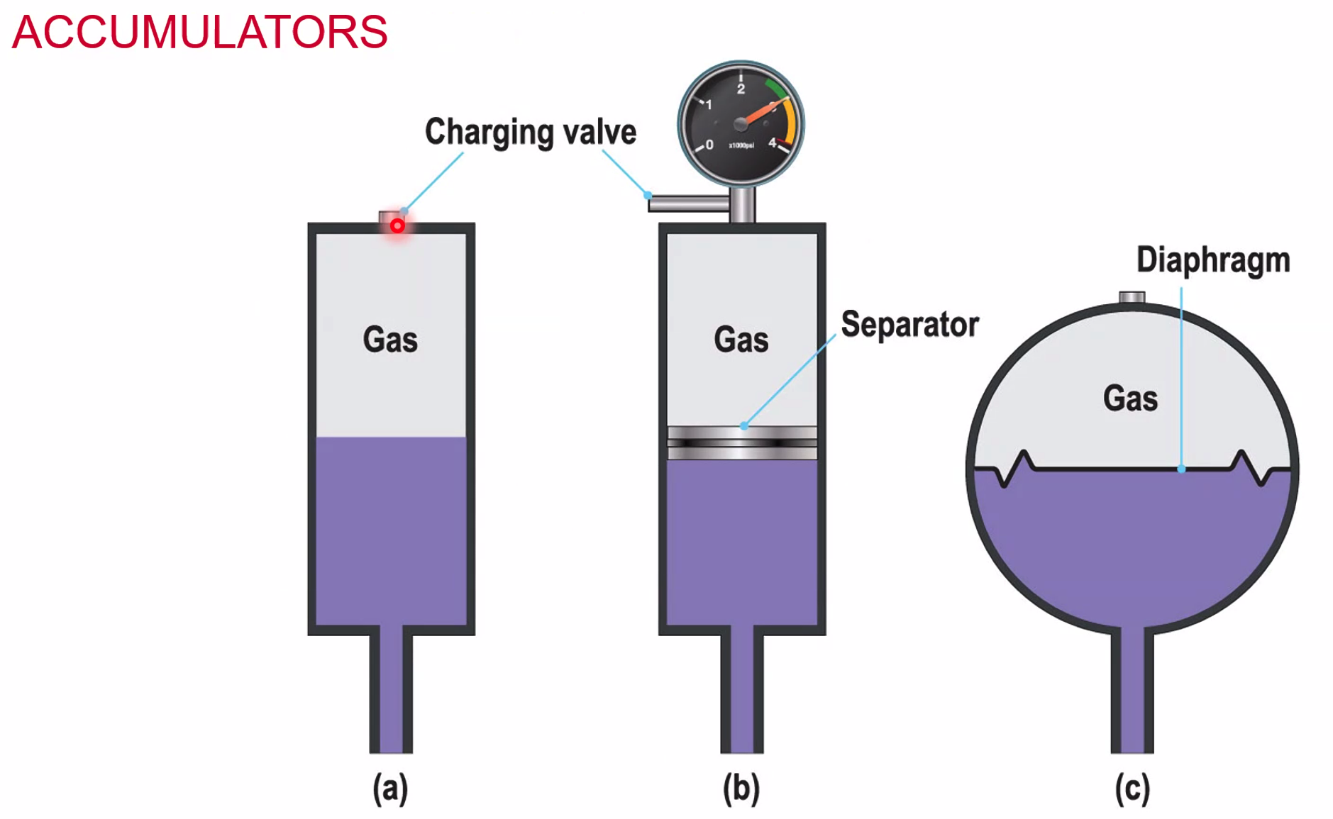
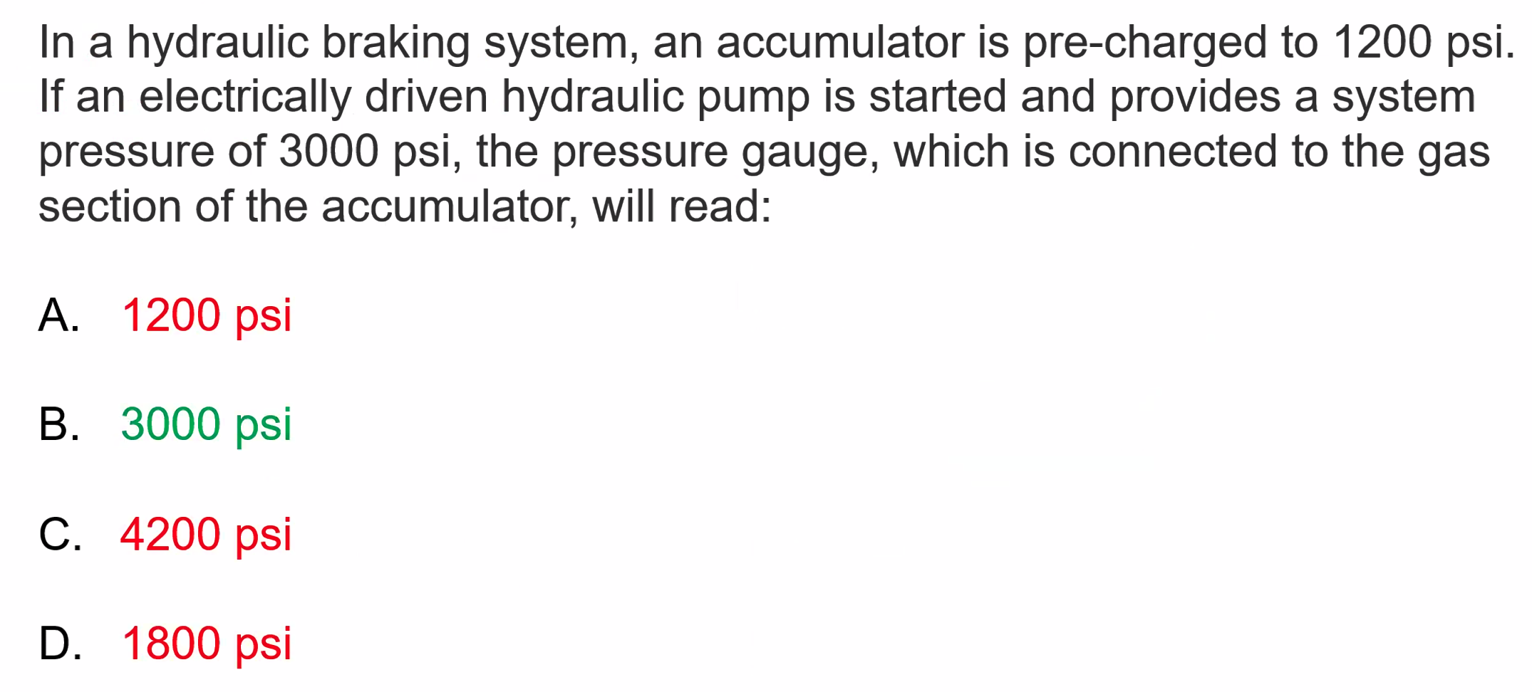
Nitrogen is used as the gas, because it won’t support a flame, it’s inert.
Rotary Selector Valve
Allows the channeling of fluid to create a reversible system / allows the reversing of an actuator.
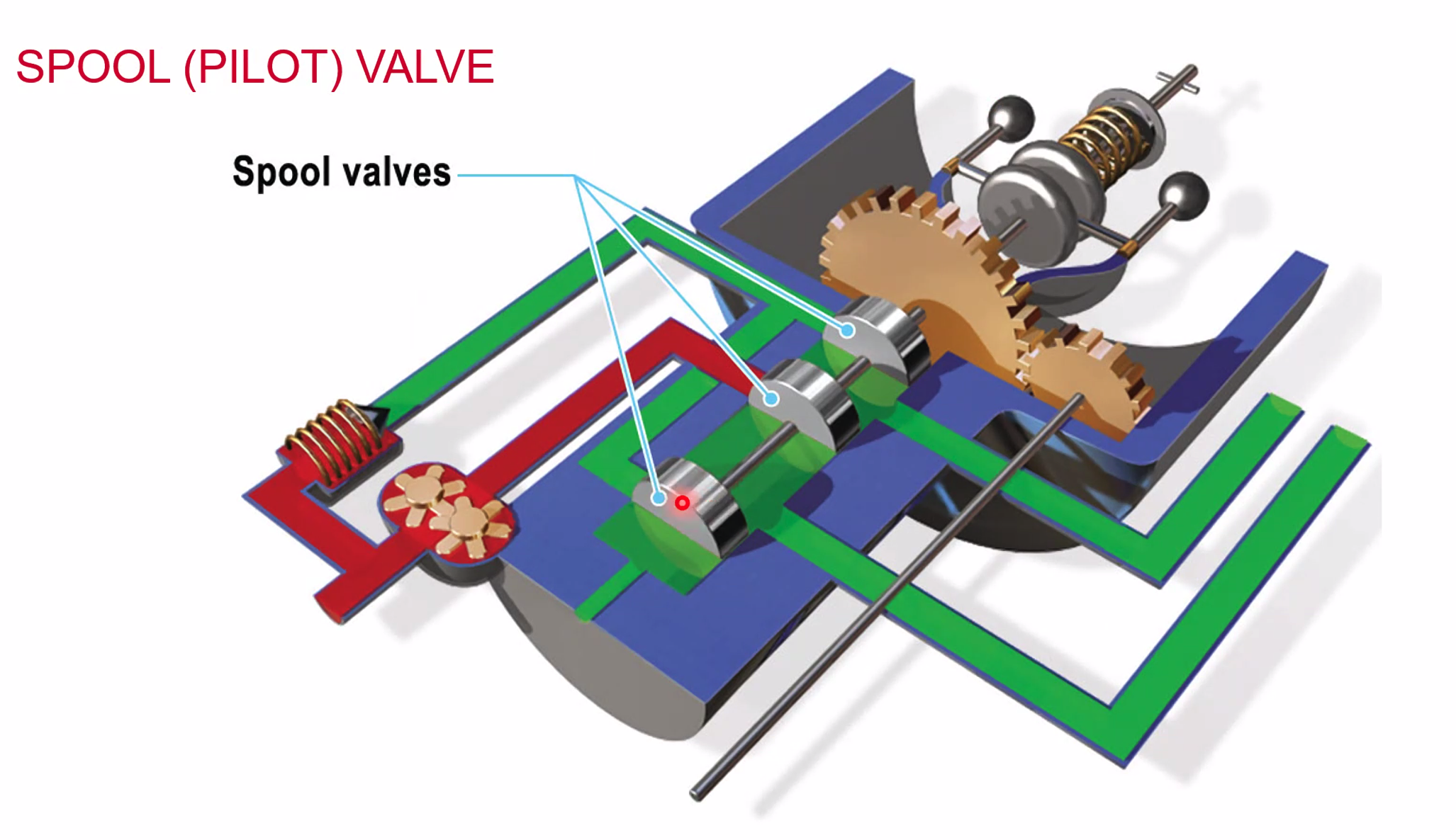
The Spool Valve is often used on a constant speed prop - the balls at the top will flow outwards moving the entire unit upwards.
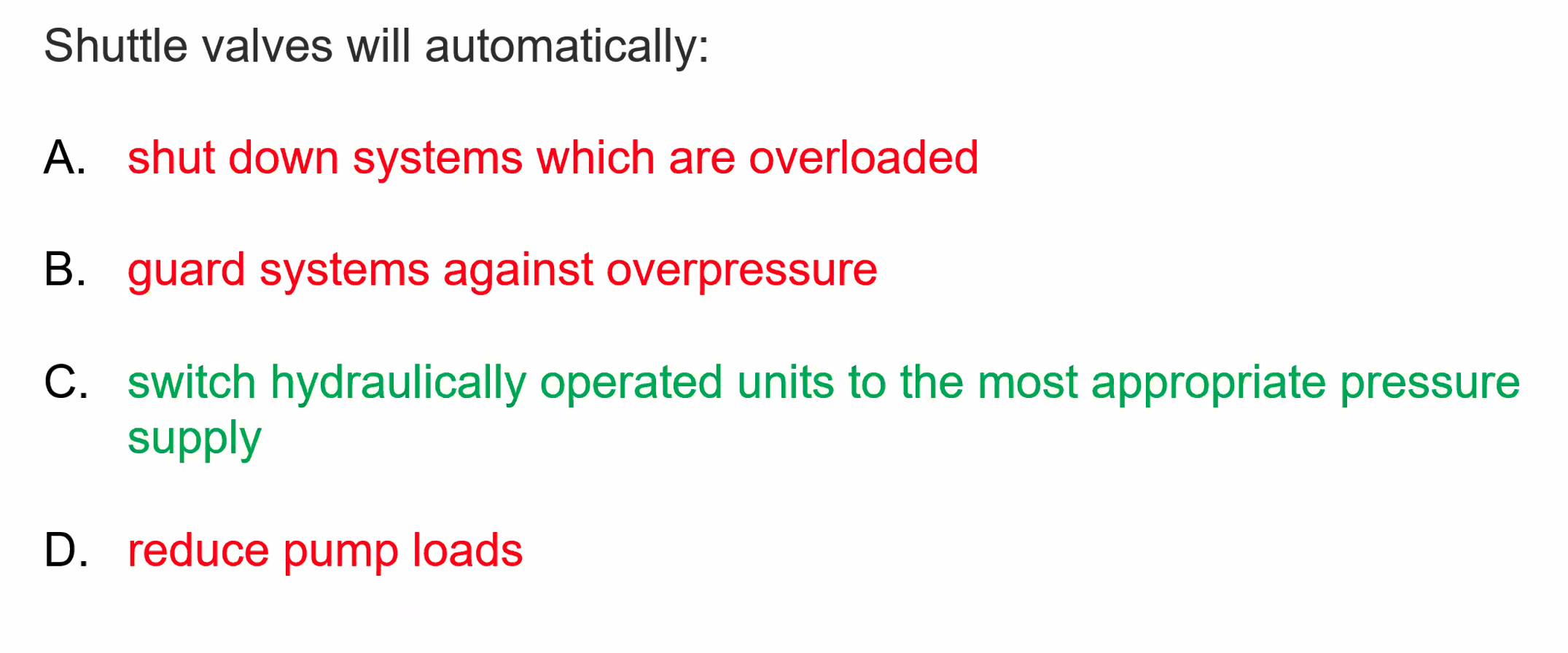
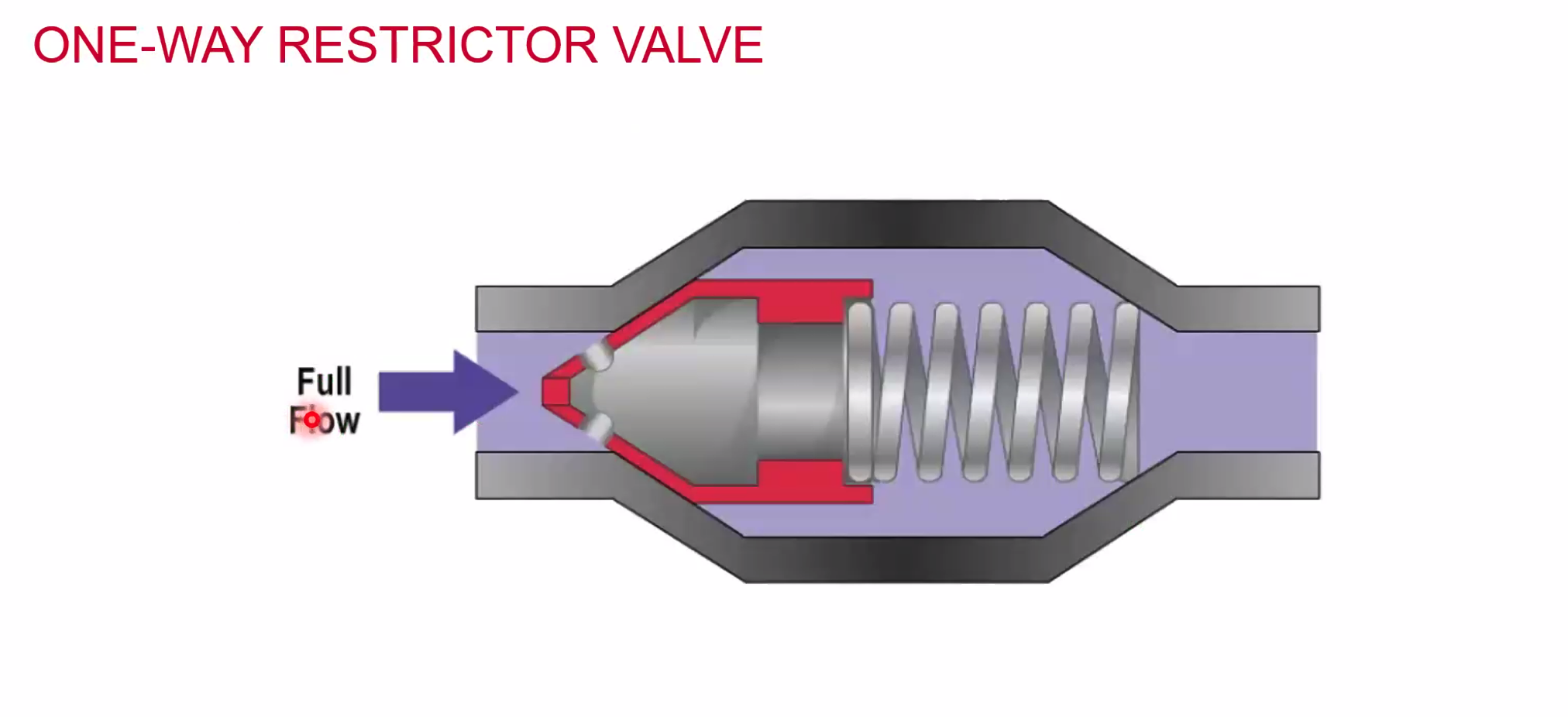
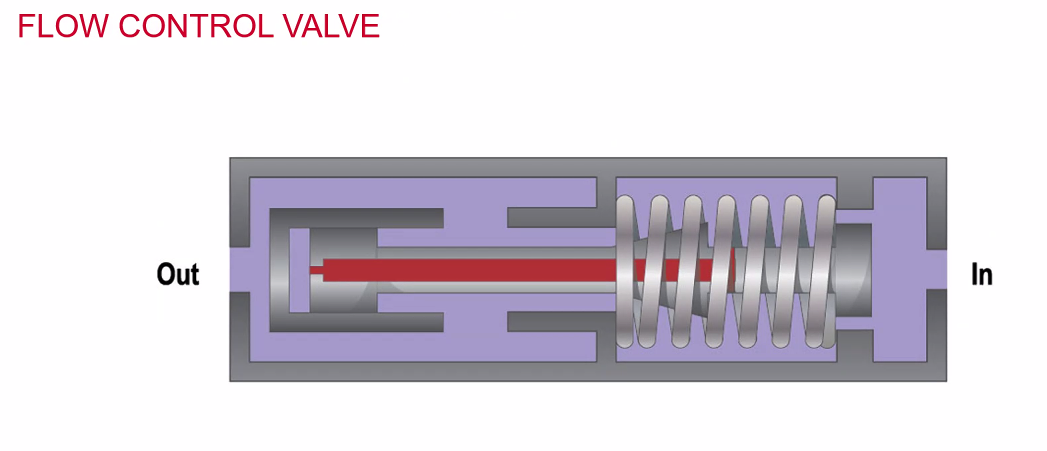
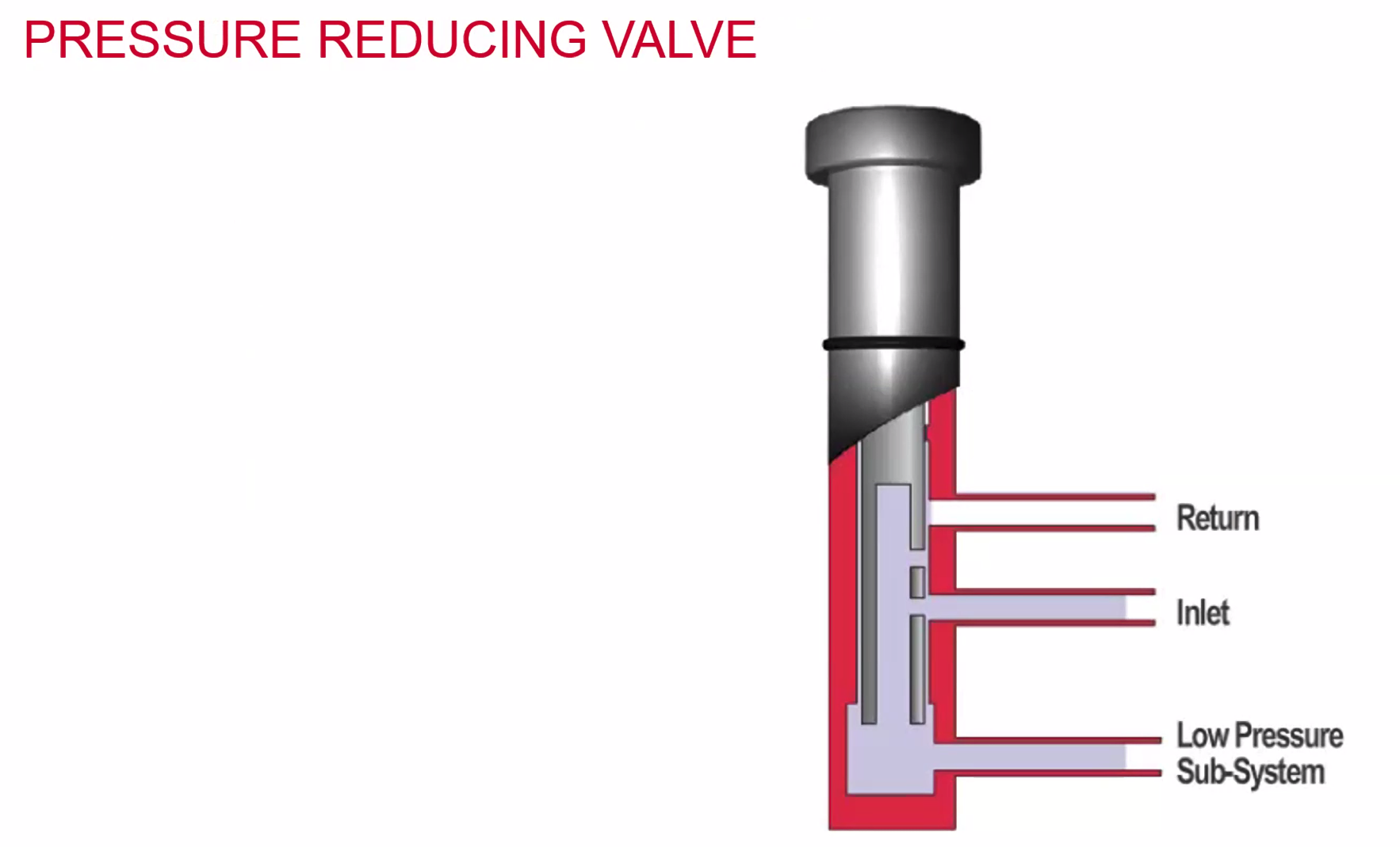
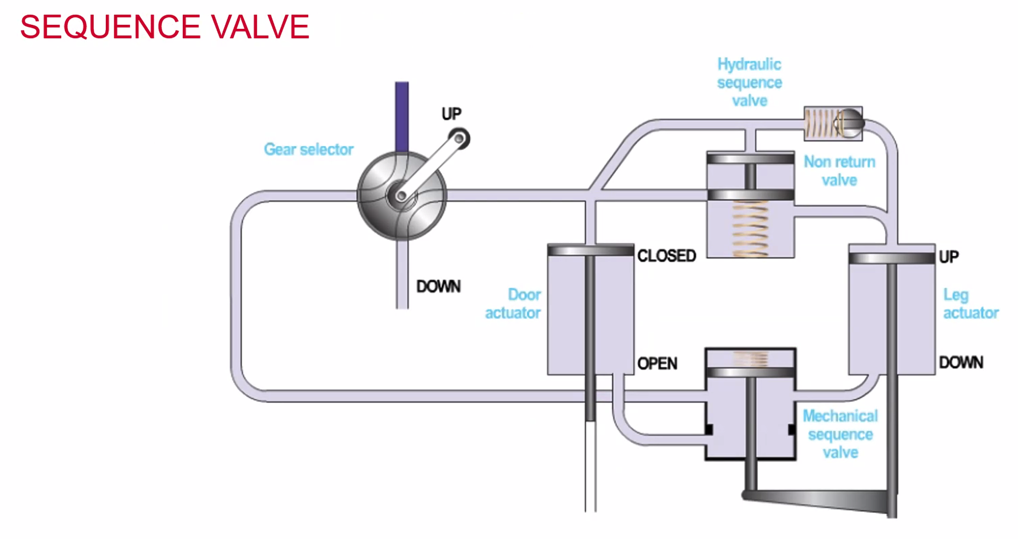
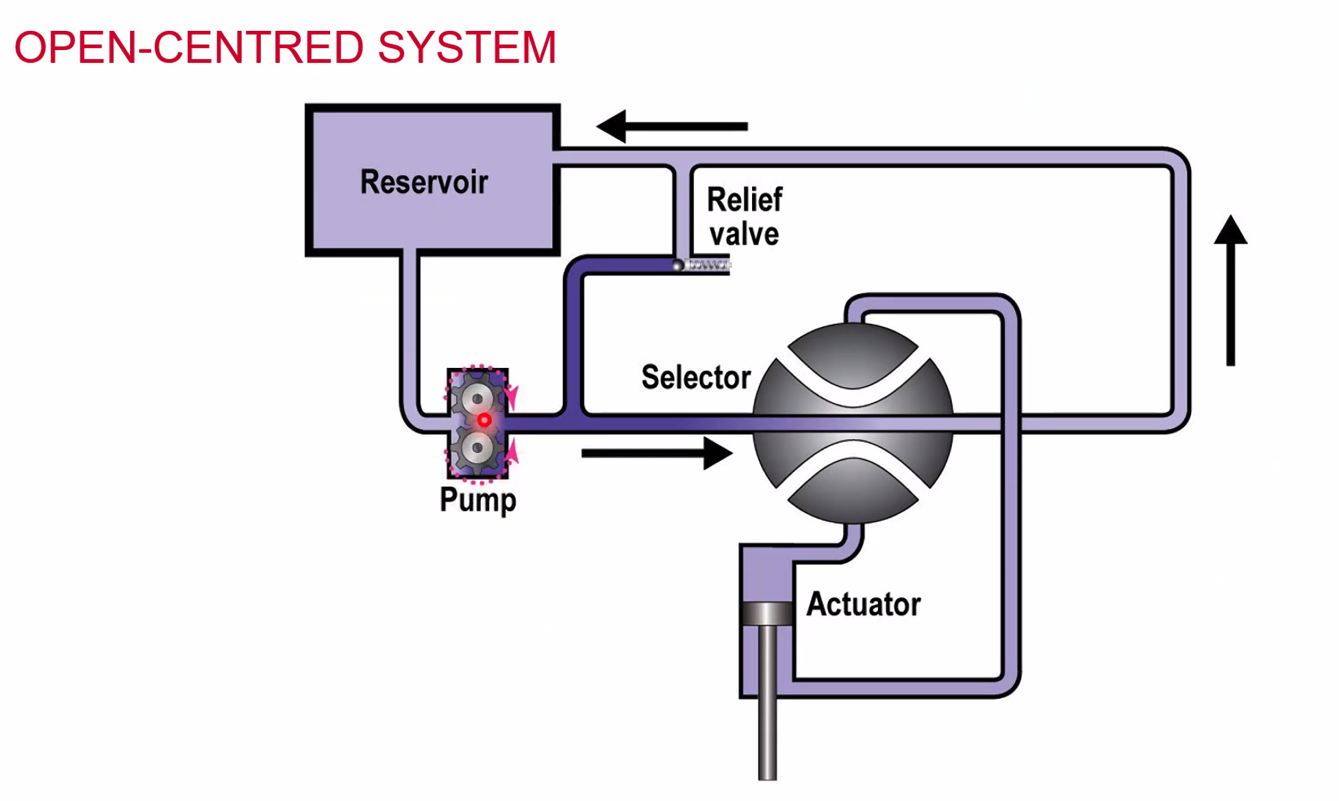
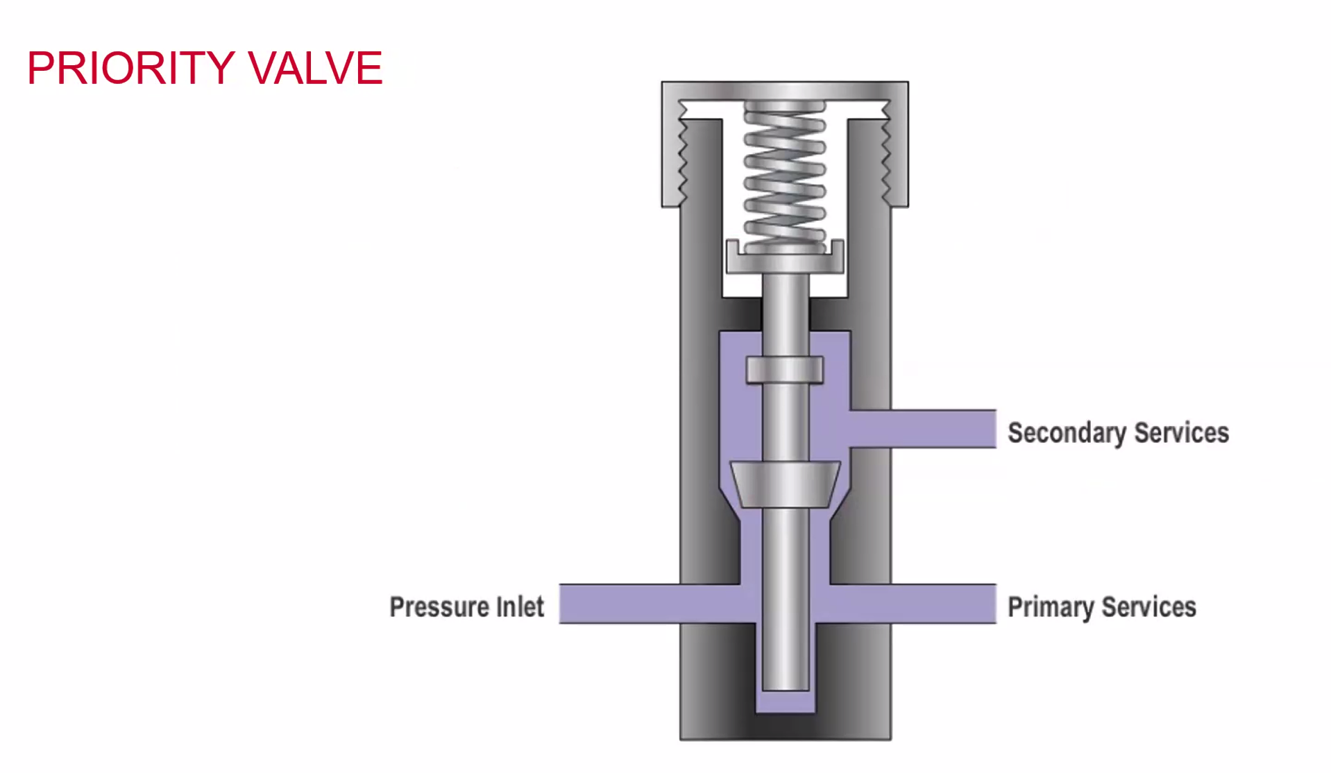
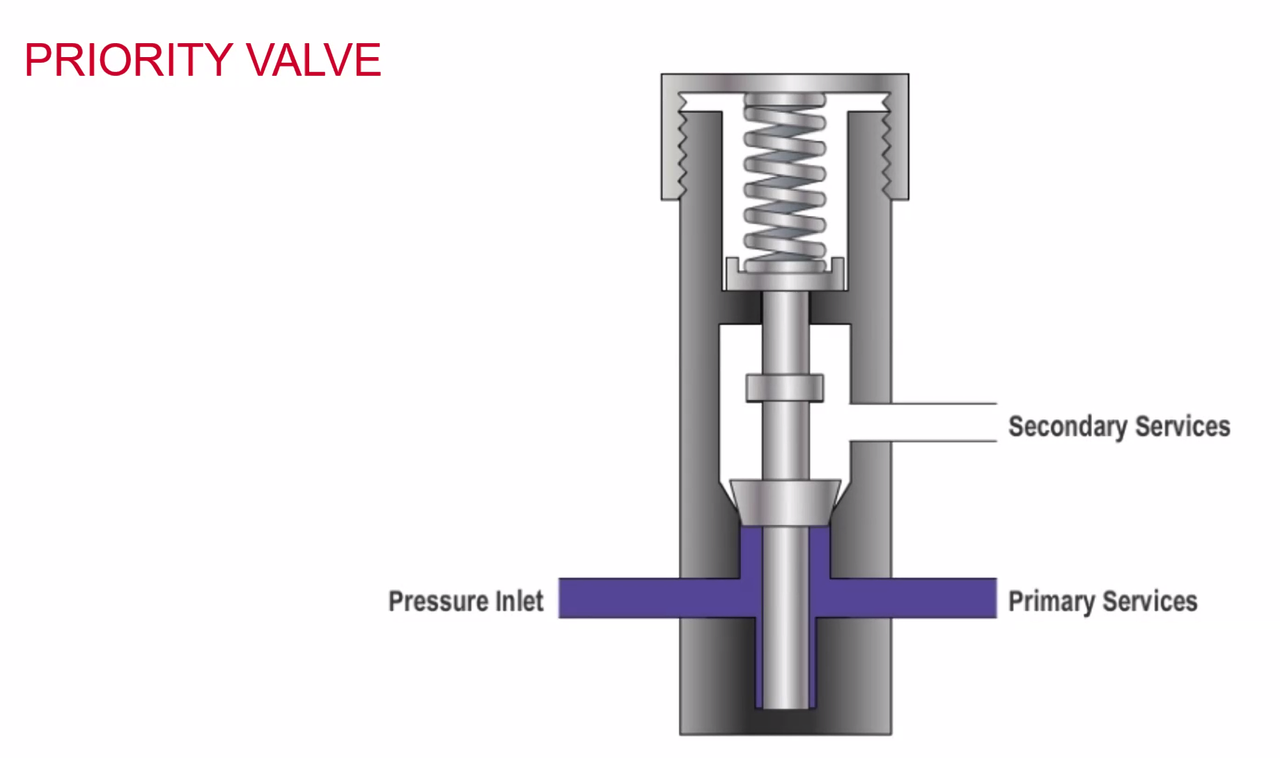
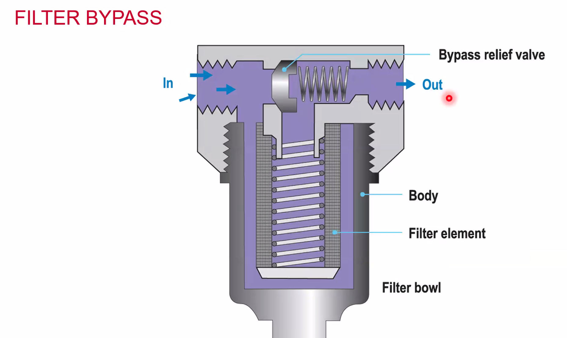
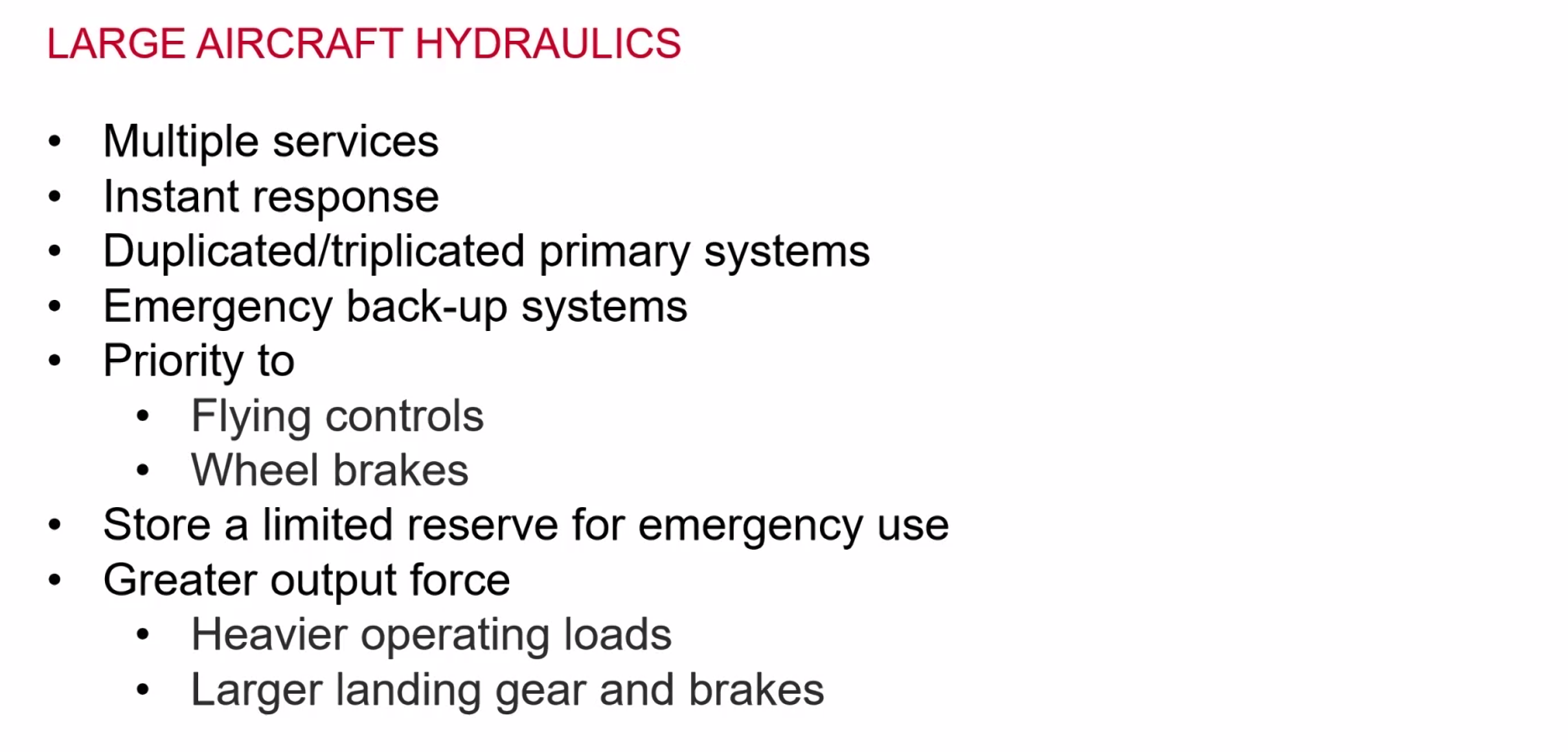
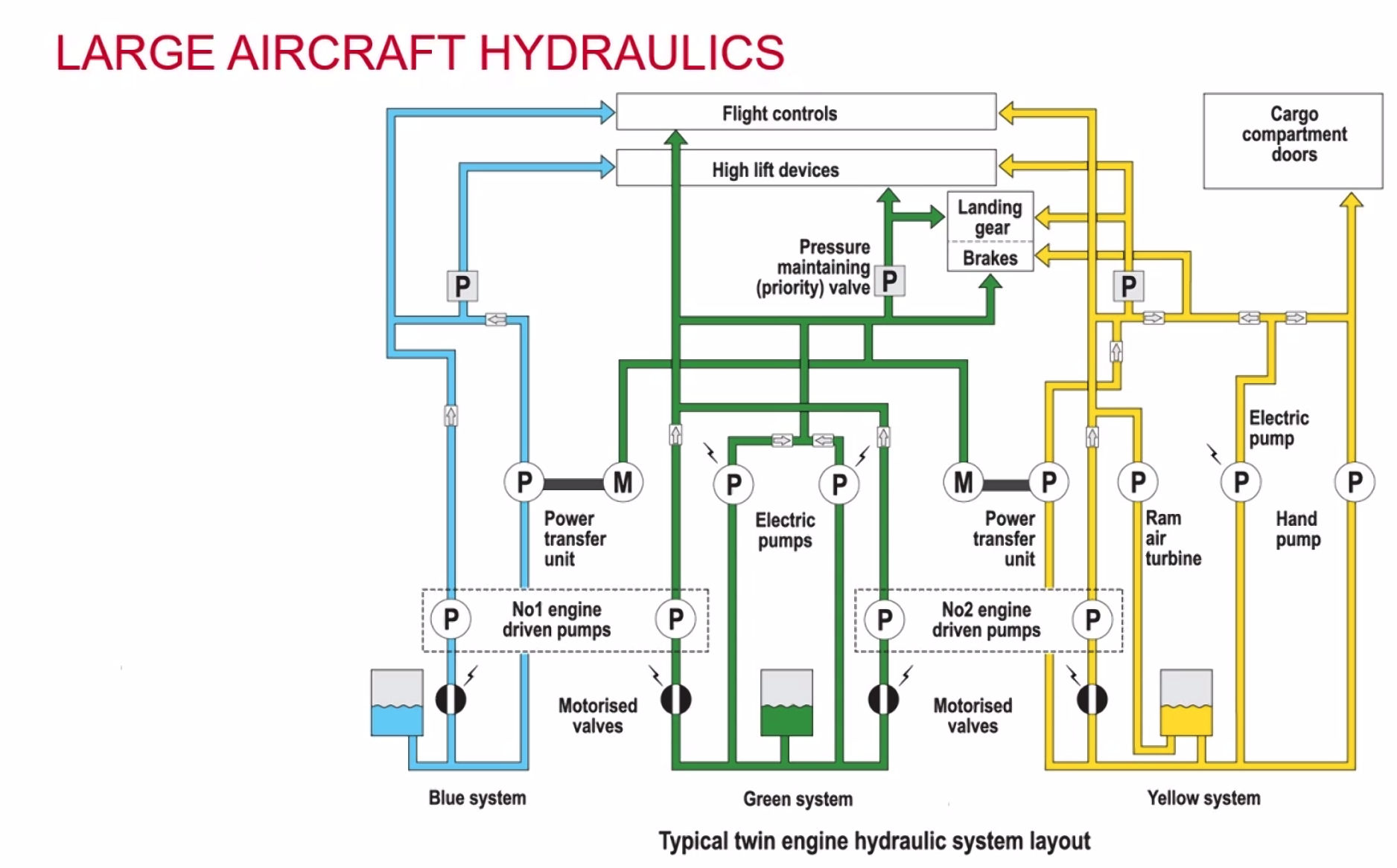
Alternative Hydraulic Power Sources
- Power Transfer Units (PTUs)
- Air turbine motors (bleed air)
- AC Powered pumps (lower capacity)
- Ram Air Turbine (RAT)
- Hand Pump (ground/emergency)
Power Transfer Unit
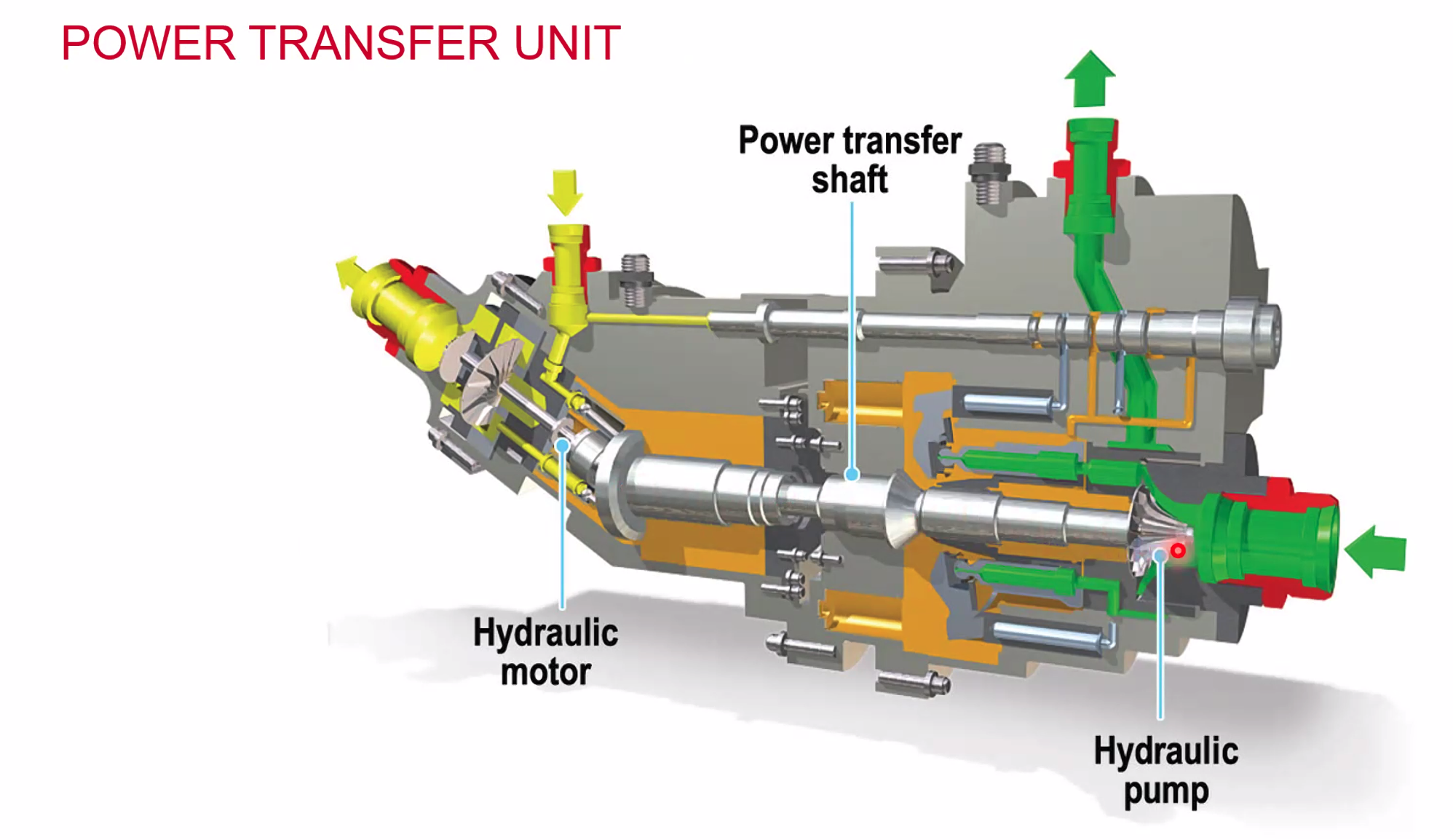
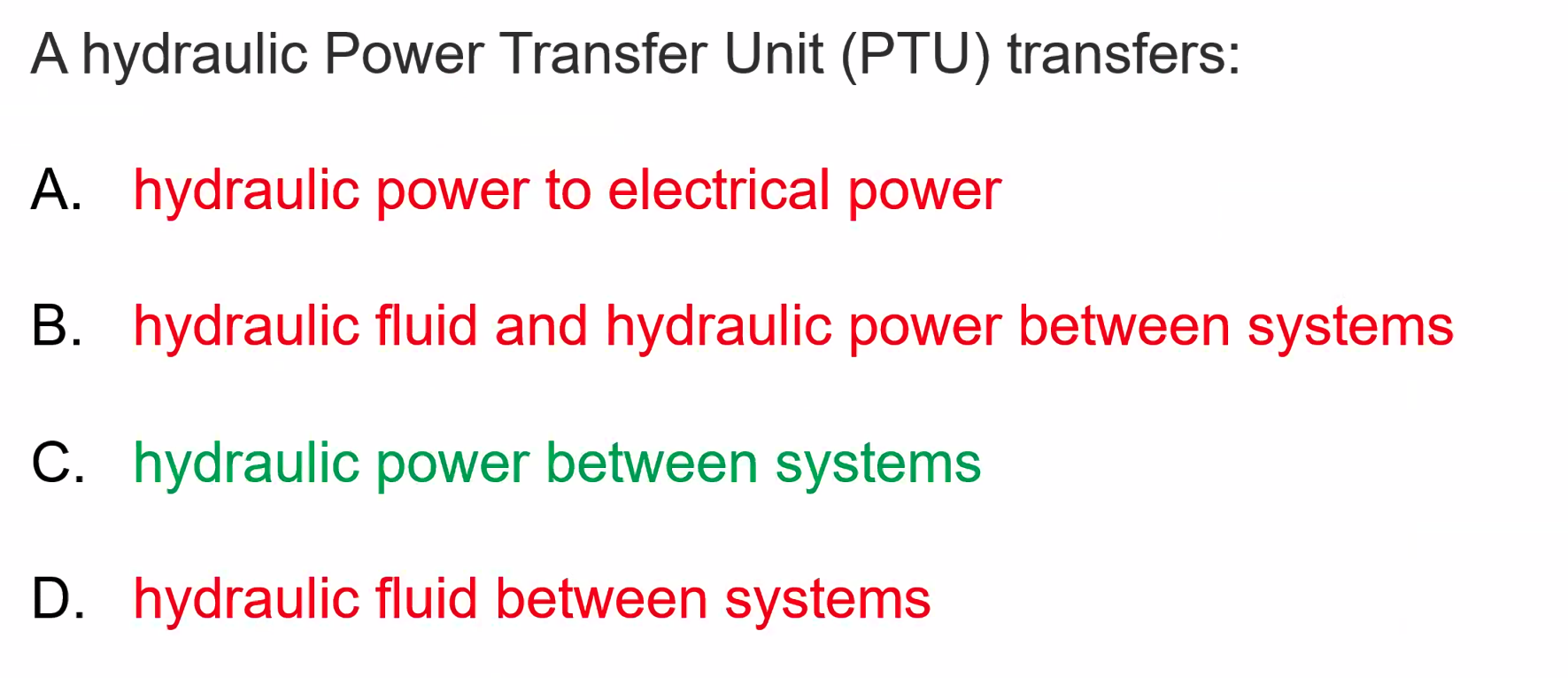
Essentially a hydraulic motor. No transfer of fluid from the green system to the yellow system (or vice versa)
Ram Air Turbine
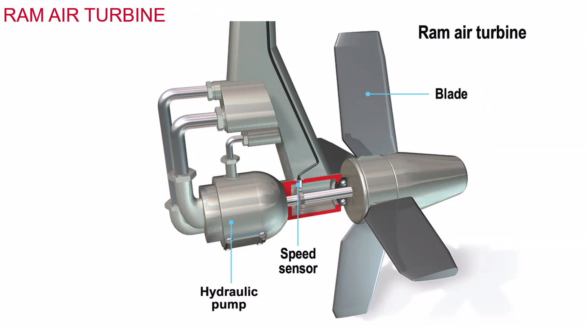
Only drops down when demanded - can be set to automatically or can be selected manually. The speed sensor allows the pilots to set the blades to a finer setting to increase / decrease the speed.
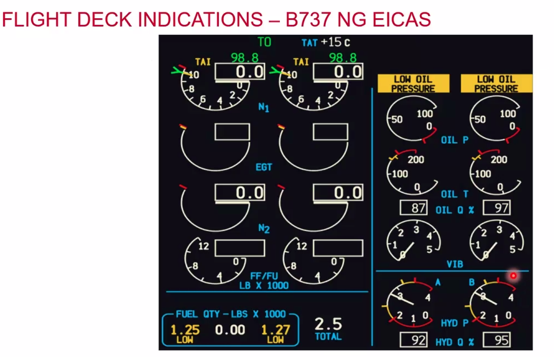
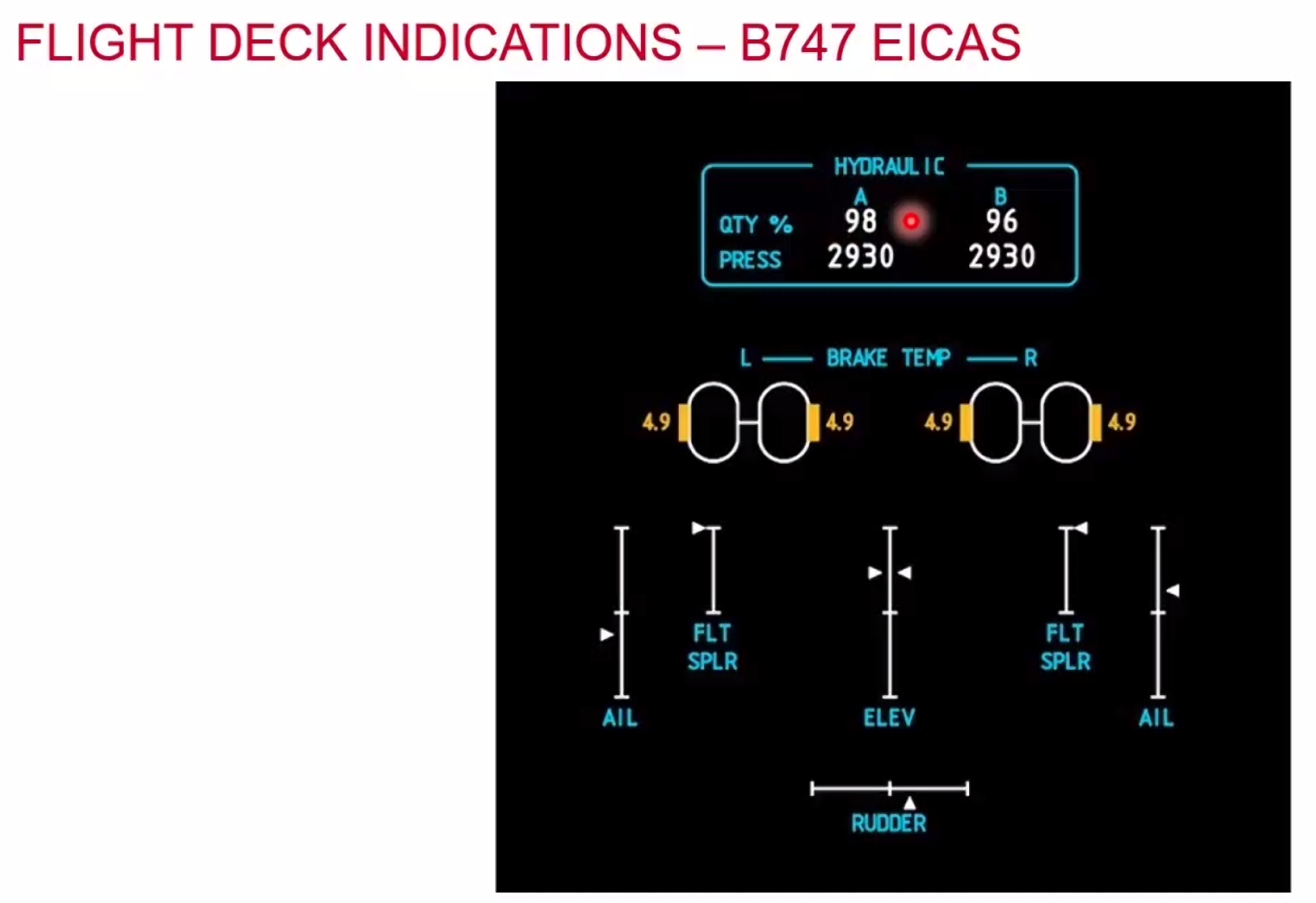
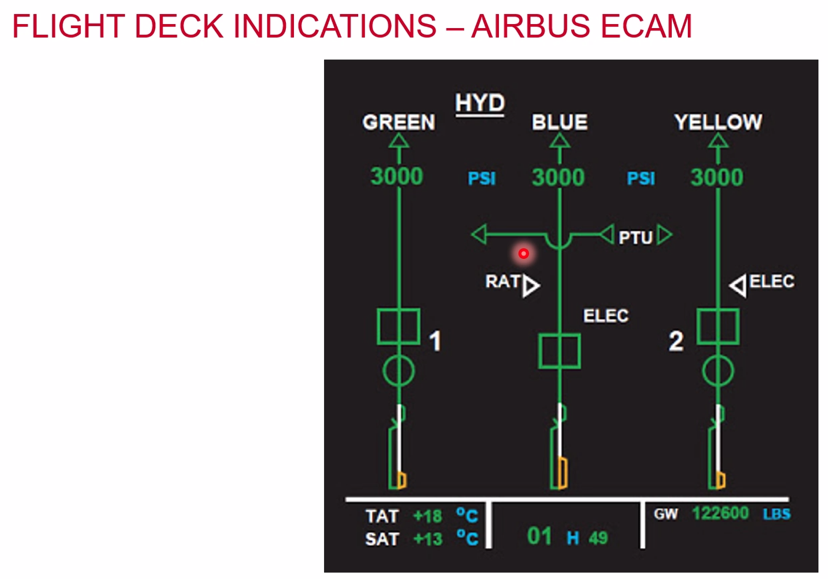
Primary Flight Controls
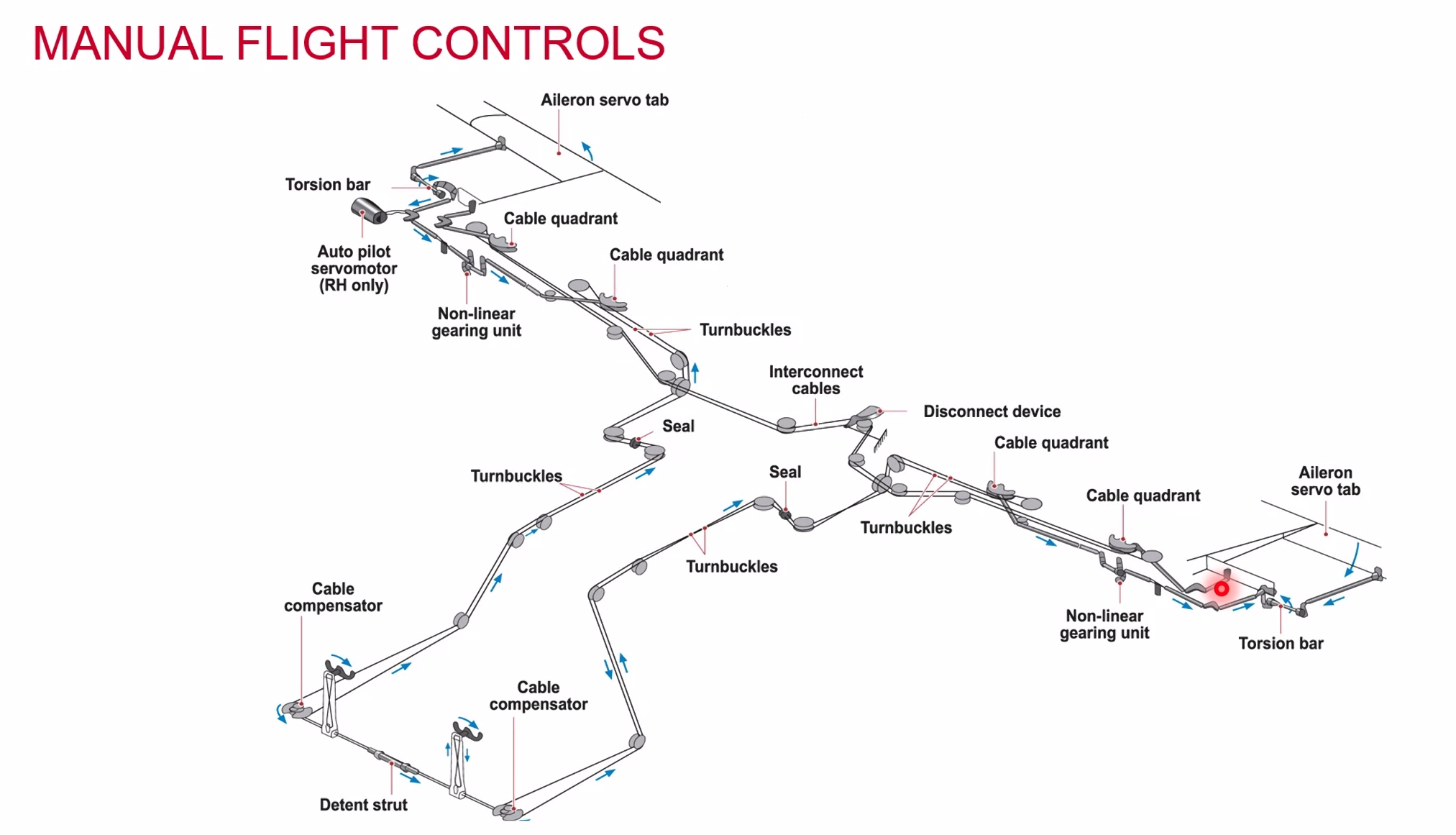
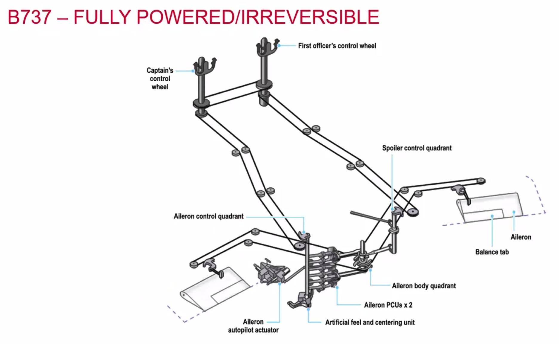
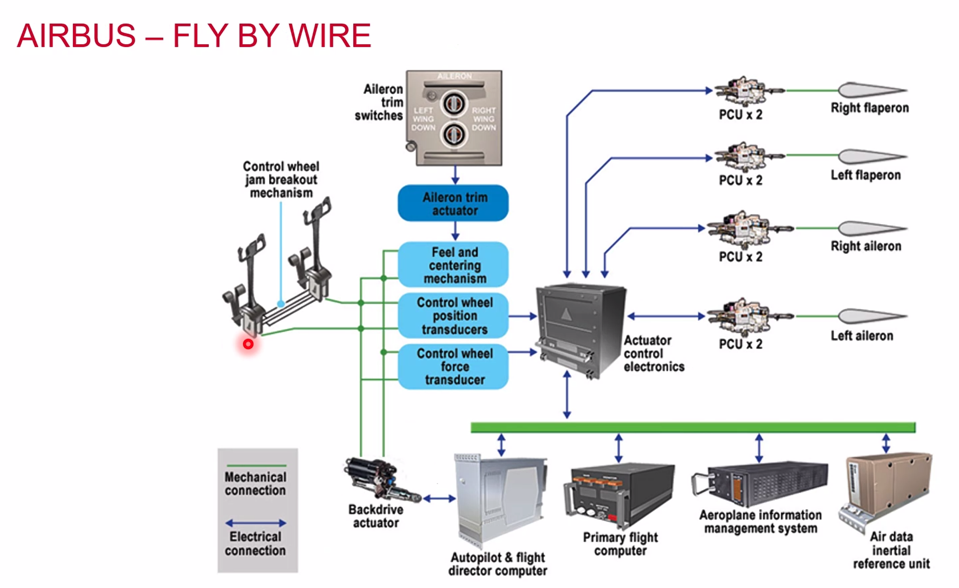
Airbus Fly by Wire Modes
- Normal Law / Mode
- Computers protect against manoeuvre limits
- Alternate Law / Mode
- Pilot workload increased
- Flight envelope protection reduced
- Many protections lost
- Direct Law
- All protections lost
- Mechanical Back up
- Pitch through trim wheel
- Roll through rudder pedal connection
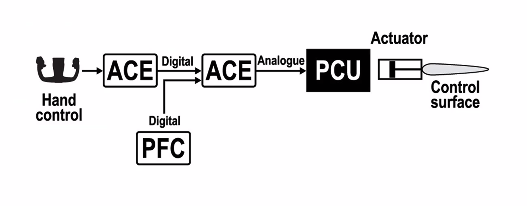
Autopilot Control
Primary Flight Control
Secondary Flight Controls
Types:
- Light Aircraft
- Flaps
- Slats
- Trim
- Large Aircraft
- Flaps
- Slats
- Load Limiting Devices
- Alpha/Speed Locks
What does the expression ‘primary flight control’ apply to?
- Elevator and the roll spoilers
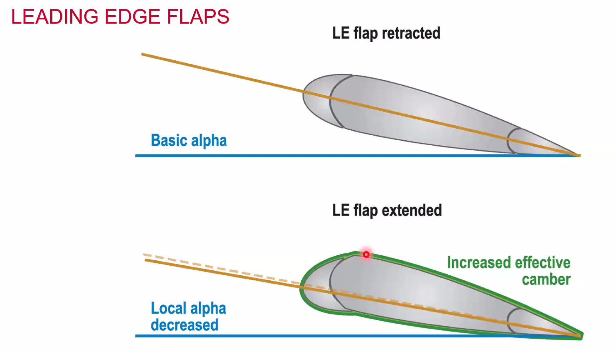
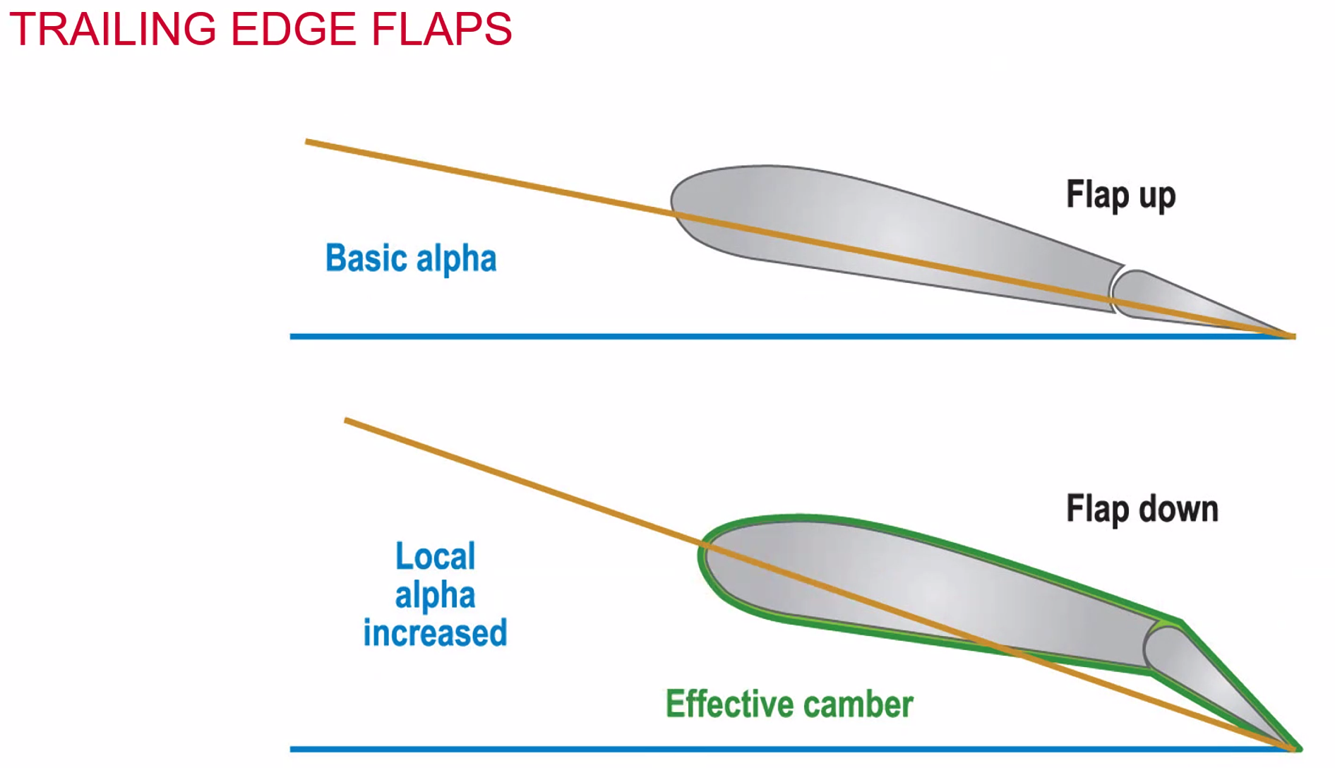
By extending the Leading Edge flaps you’re effectively decreasing the angle of attack due to the lower level of the chordline
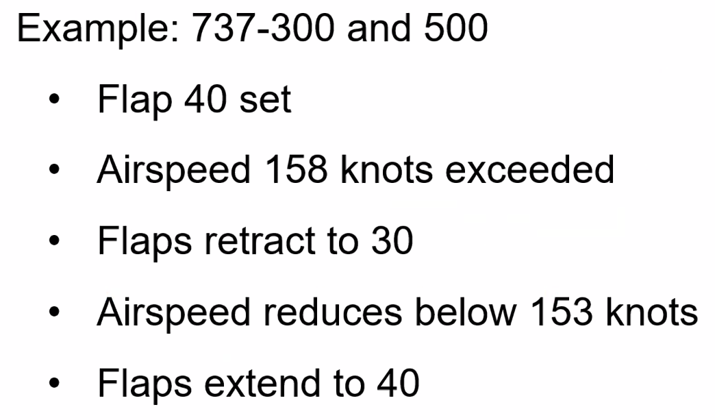
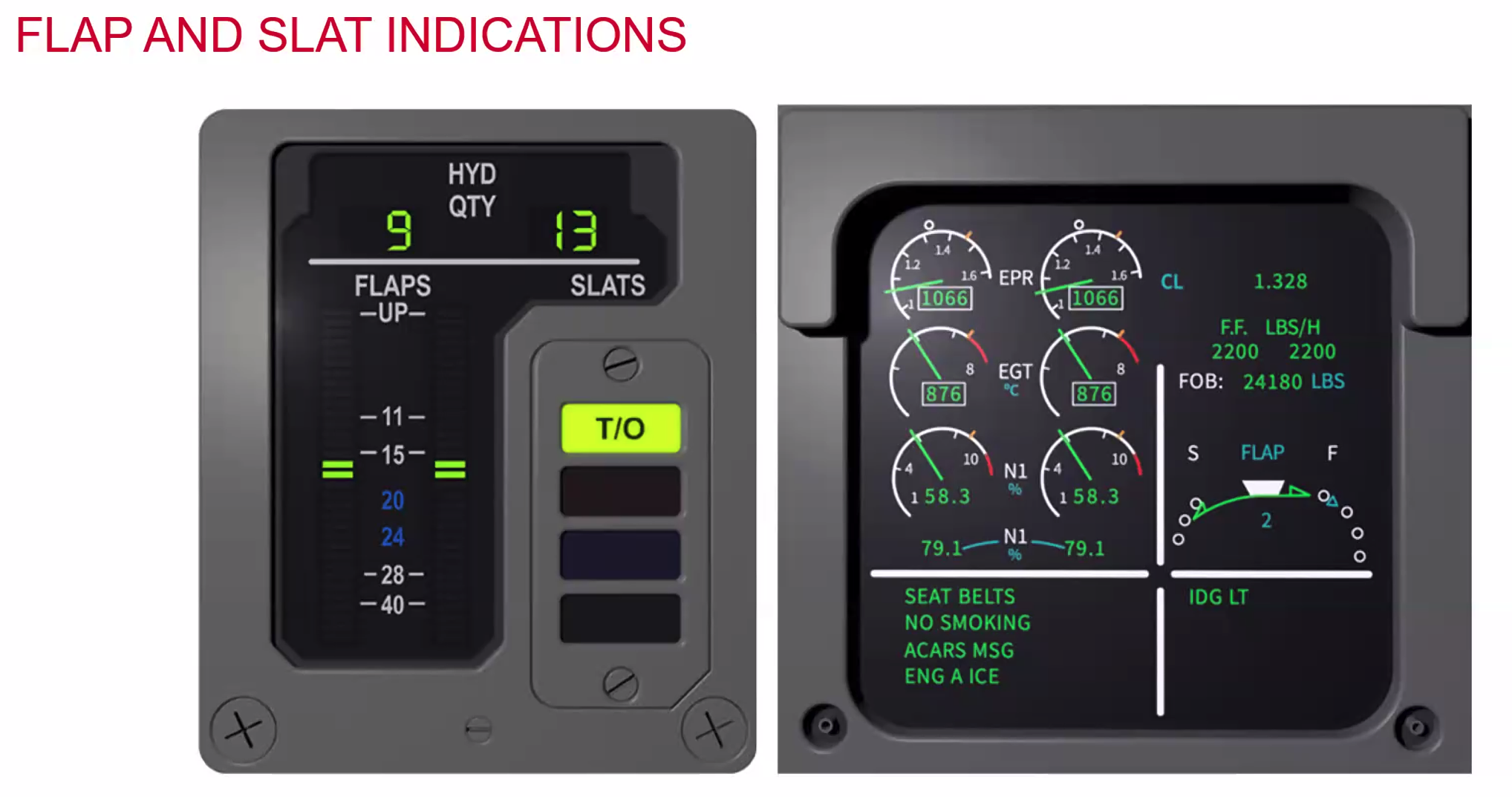
Flap Load Limiters
- Automatically protects flaps against overload
- Speed linked
- Flap lever does not move
- Flap indication moves
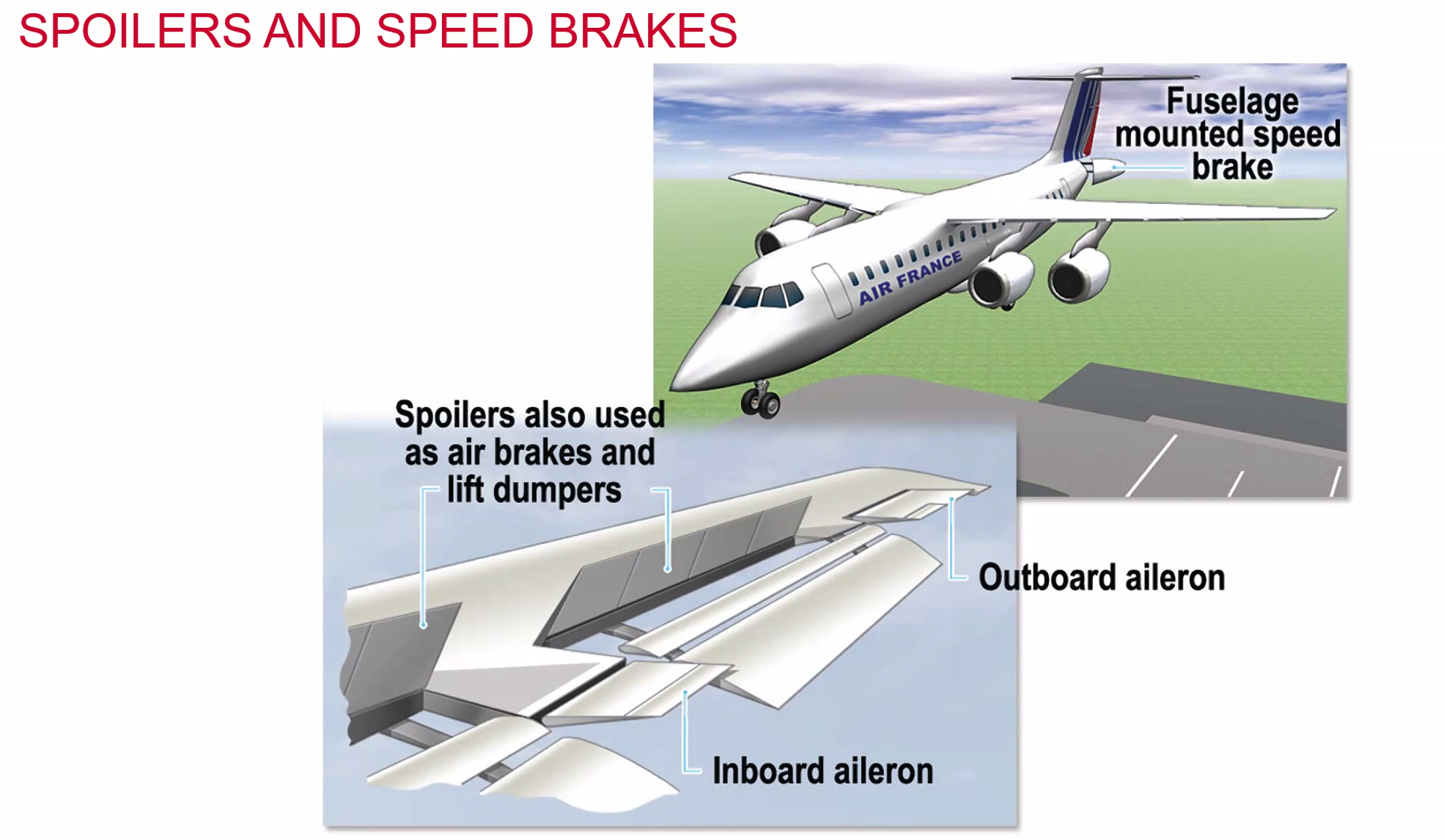
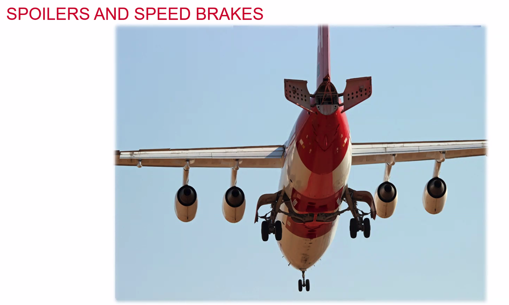
- Can also use the speed brakes on the ground, when the wheels touchdown they can automatically deploy to dump all of the lift.
- When in use as roll spoilers they don’t come up anywhere near as much. Small movements.
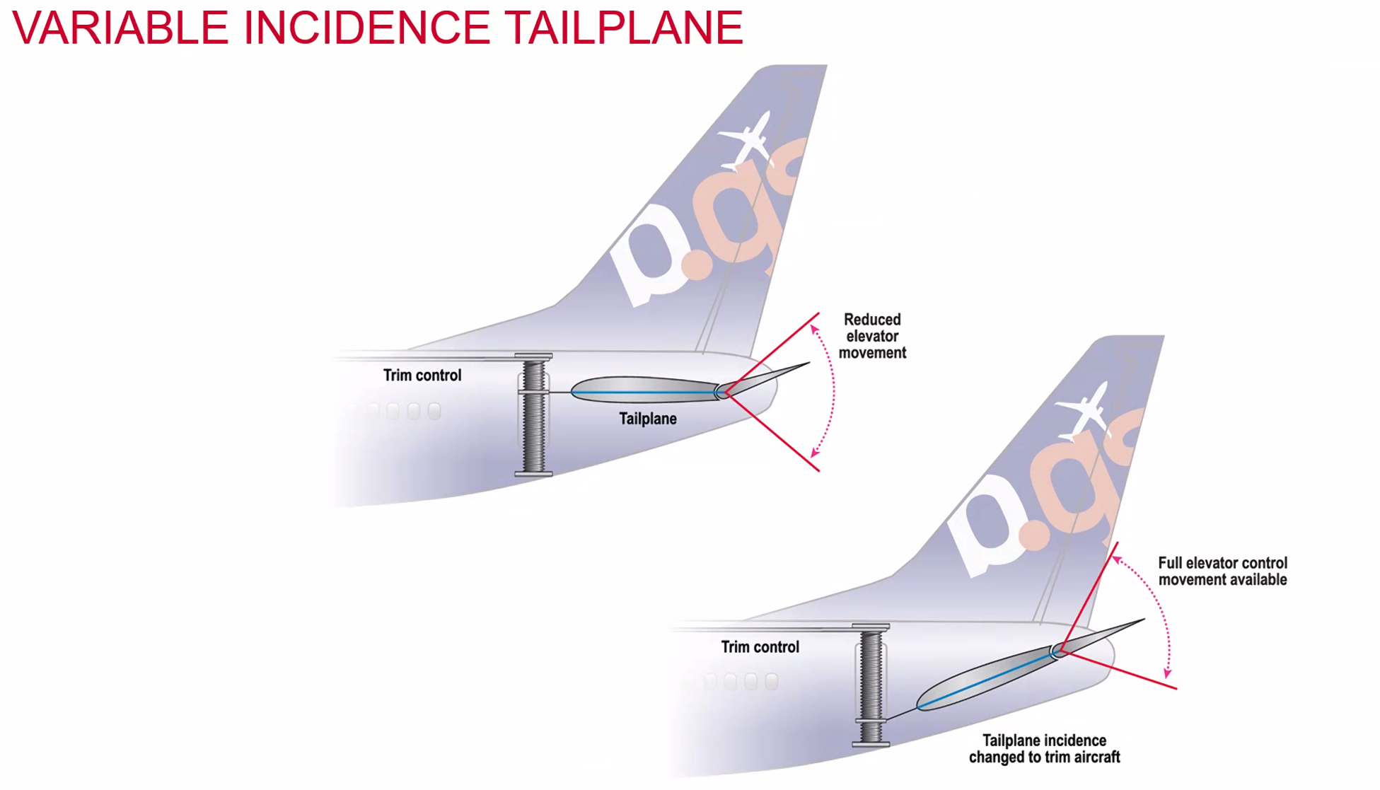
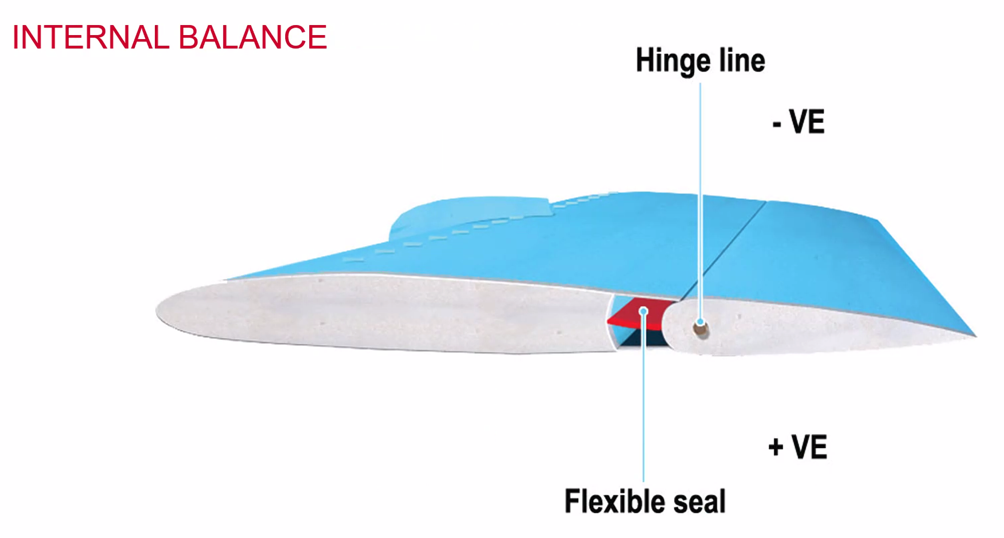
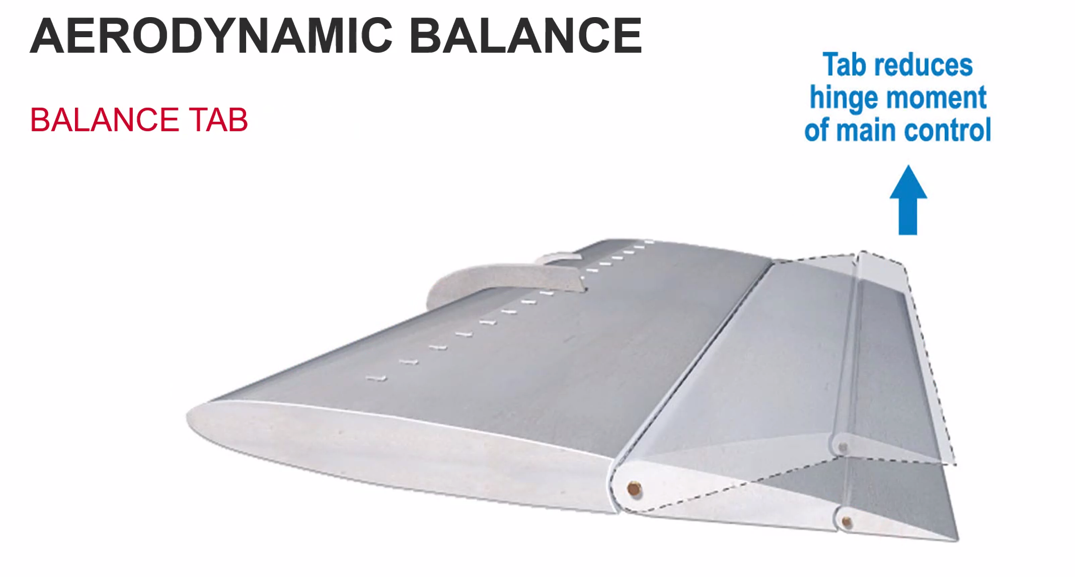
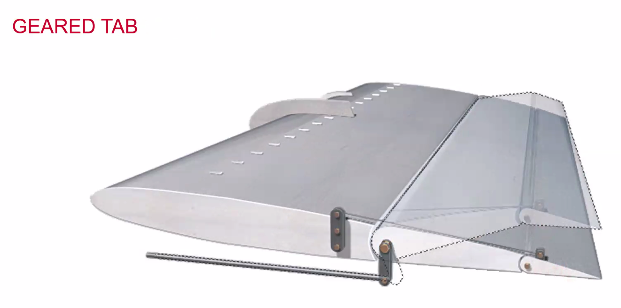
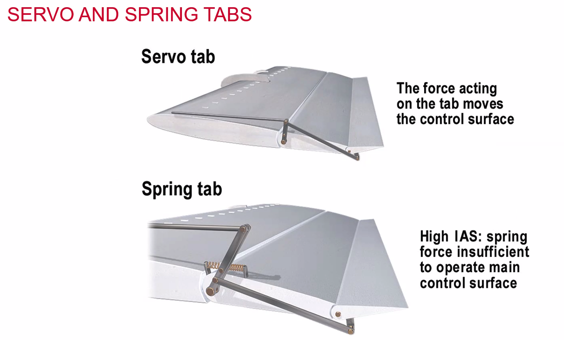
Aerodynamic Balance
Methods:
- Horn Balance
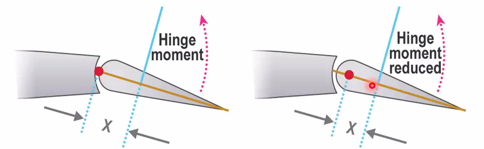
- Inset Hinge
- Internal Balance
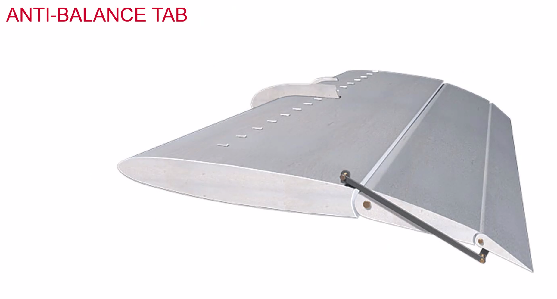
- Balance Tab - moves in the opposite direction to flight control
- Anti-balance tab - moves same as flight controls
- Servo/spring servo - moves opposite
- Trim tab - moves opposite
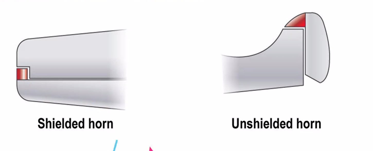
Horn Balance
- A section of the Aileron / Elevator which will protrude into the airflow to increase the effectiveness of the control service

Landing Gear
- Types and configuration
- Fixed
- Retractable
- Shock Absorption
- Retraction and Extension
- Steering
- Brakes
- Wheel and park brakes
- Anti skid
- Automatic Braking
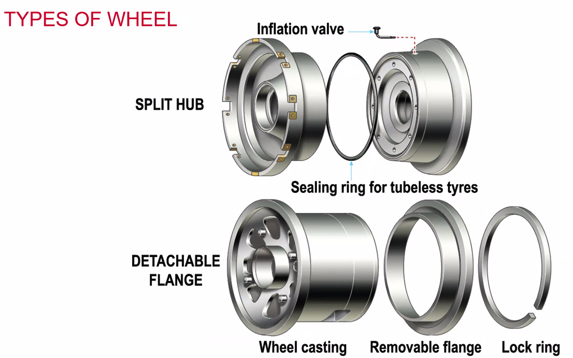
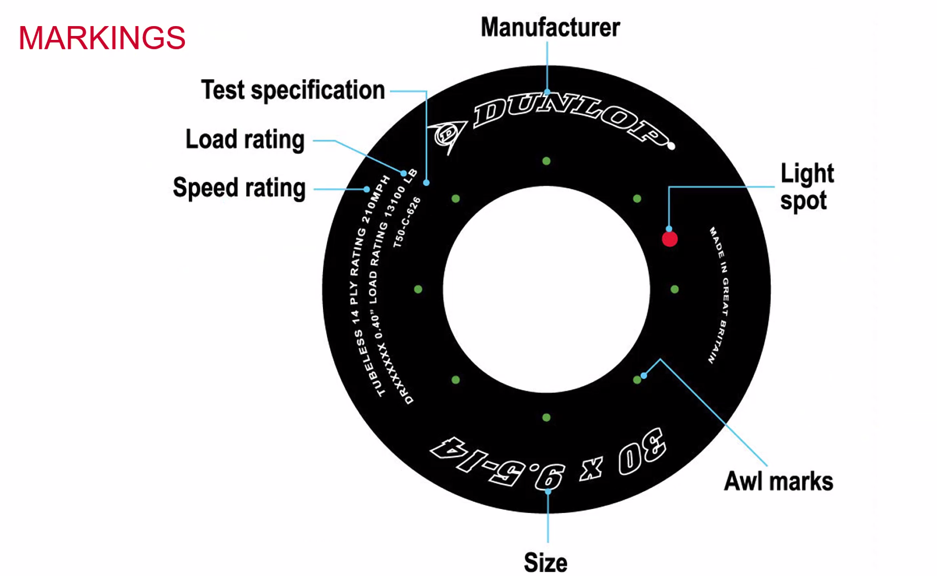
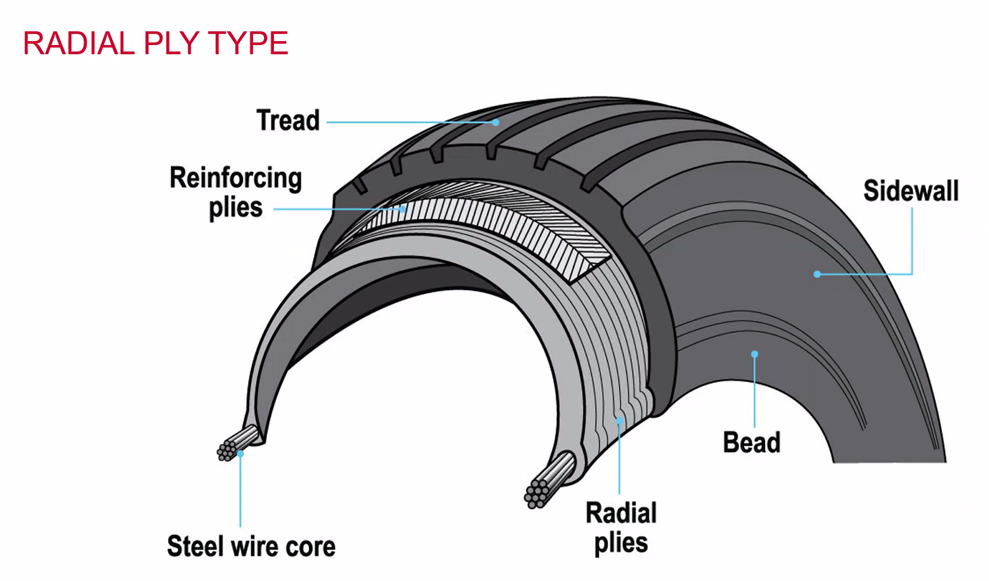
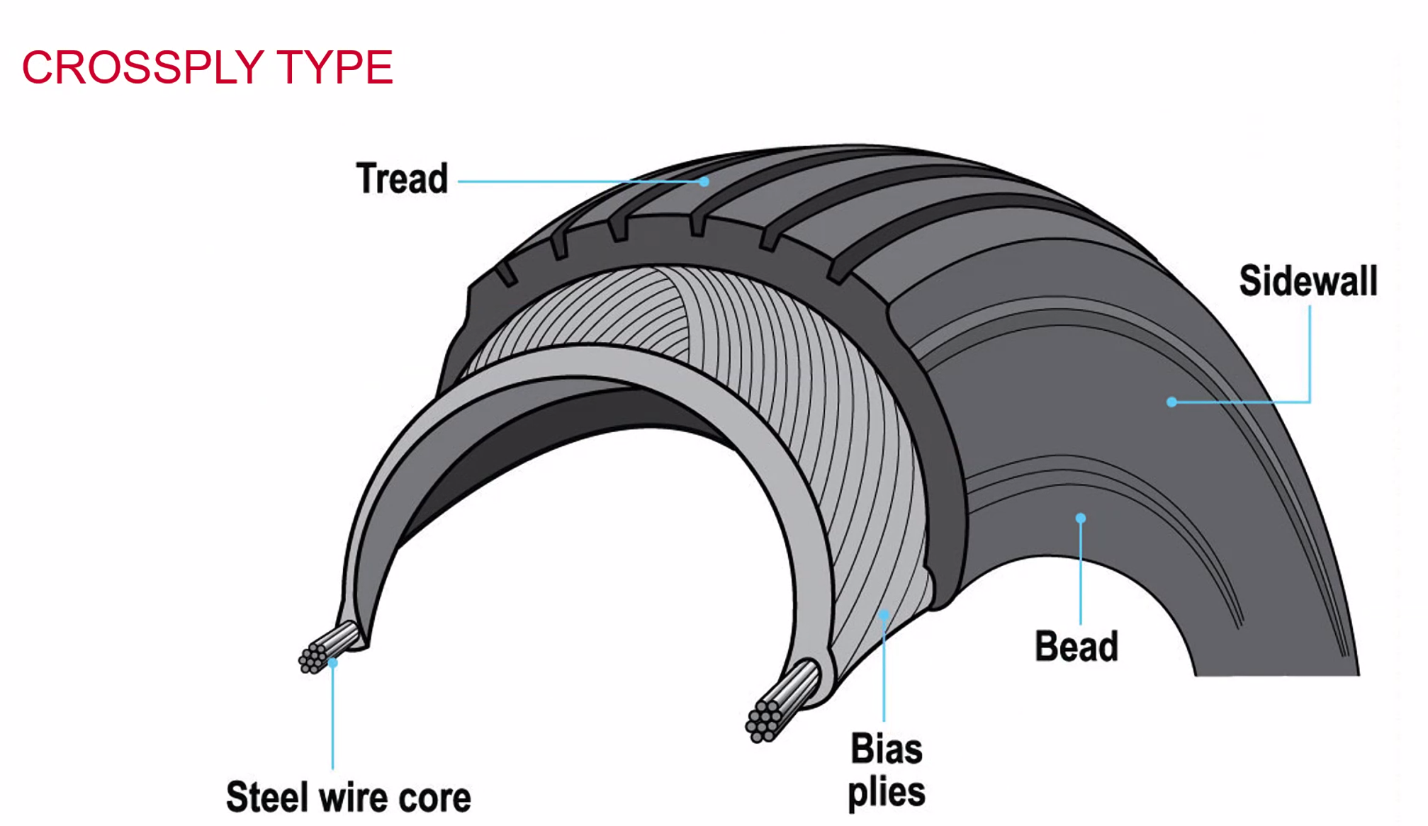
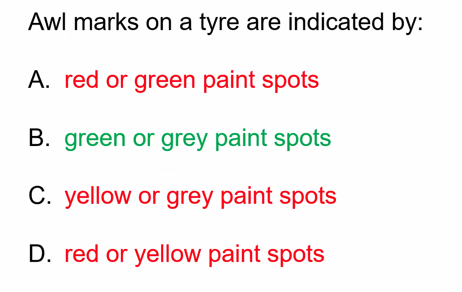
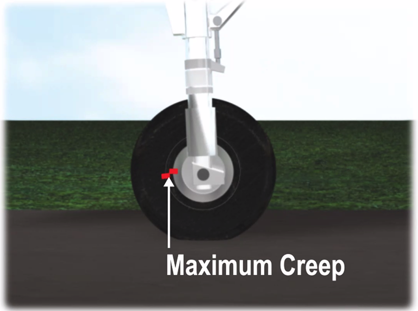
- Wheels and Tyres
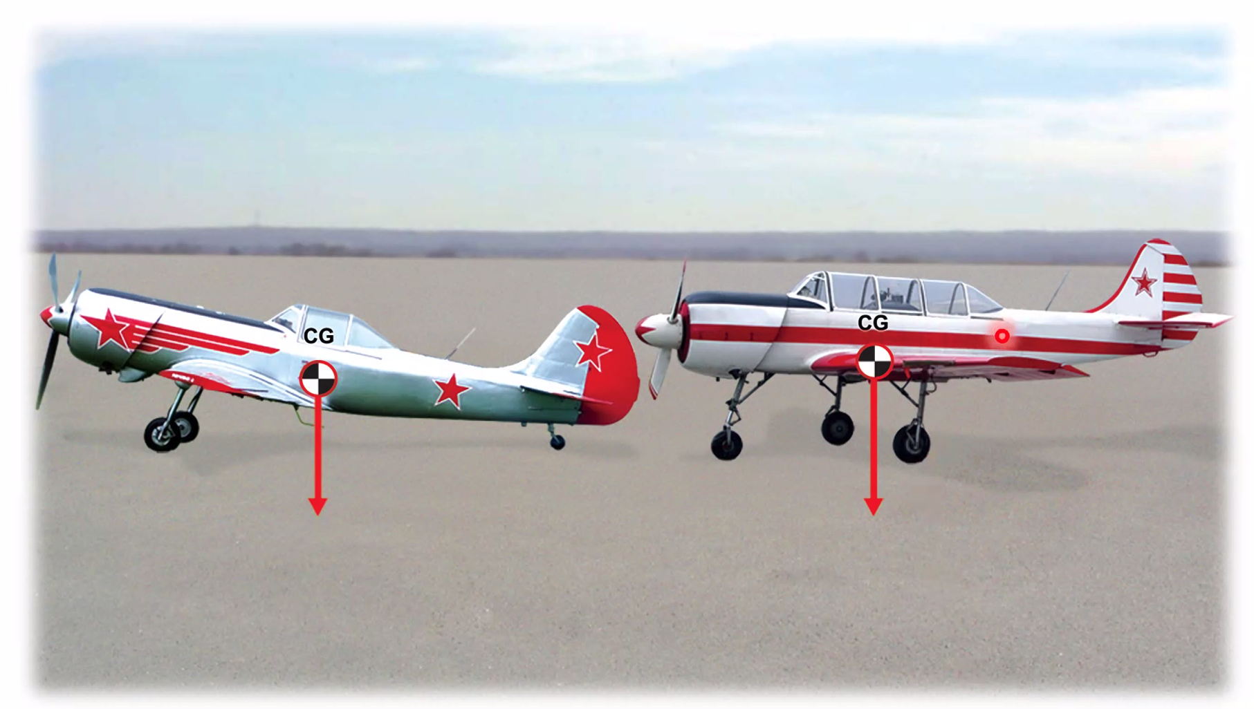
Design is always aimed to have the CofF within the footprint of the landing gear.
Both Taildragger and nose wheel aircraft have their own advantages. Nose wheel aircraft is the newer design due to the better visibility out of the cockpit.
Landing Gear
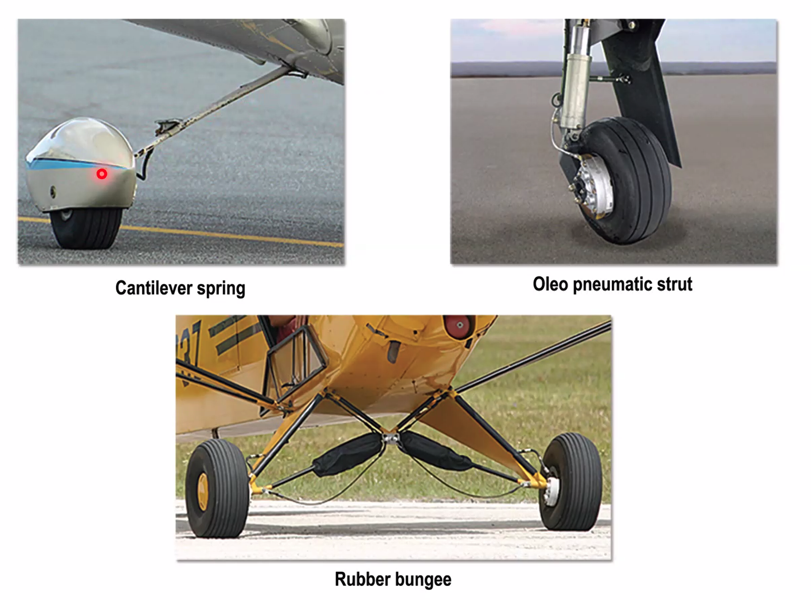
- Cantilever - the whole arm will bend to absorb the shocks / weights of landing
- Oleo Pneumatic Strut - essentially a big oleo
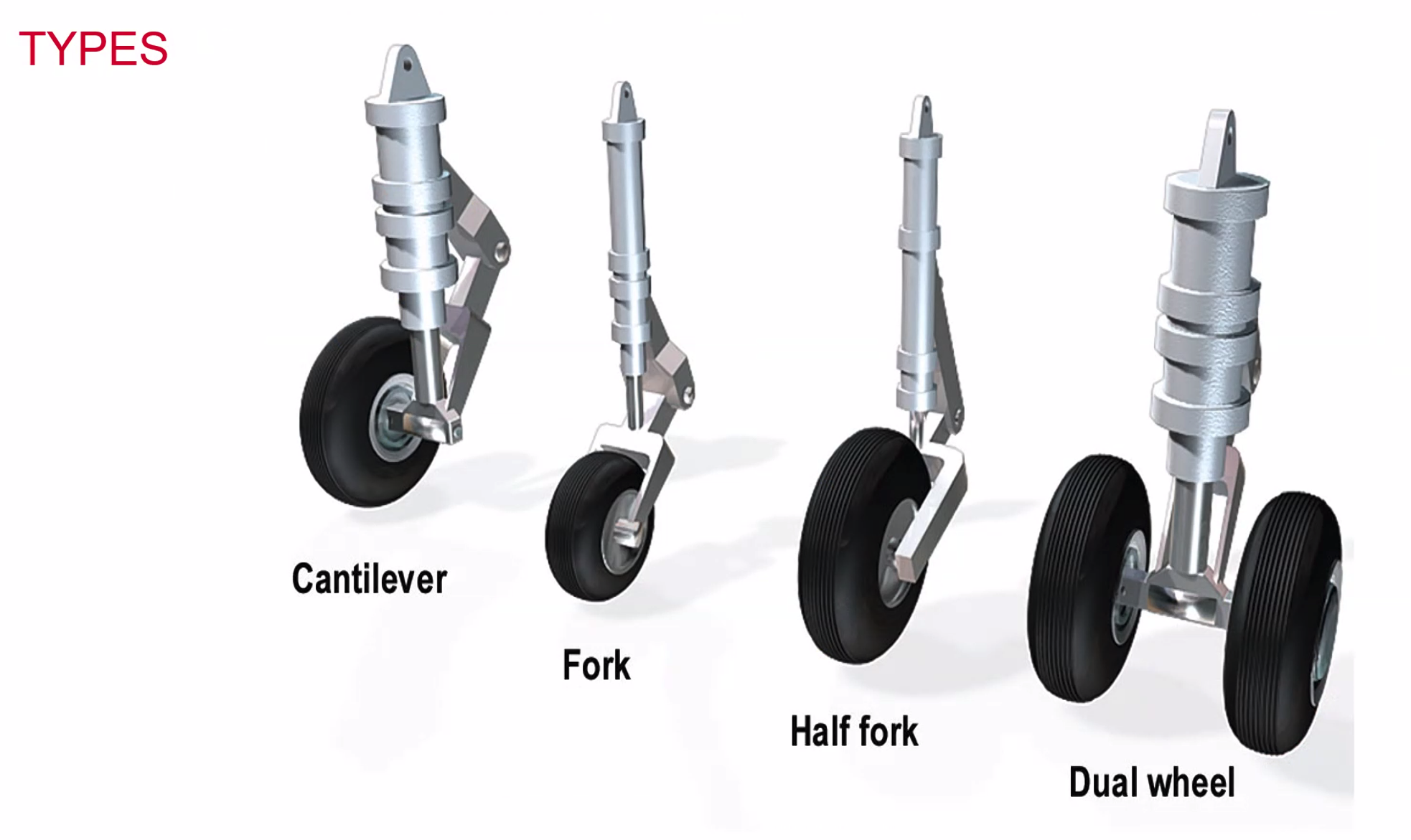
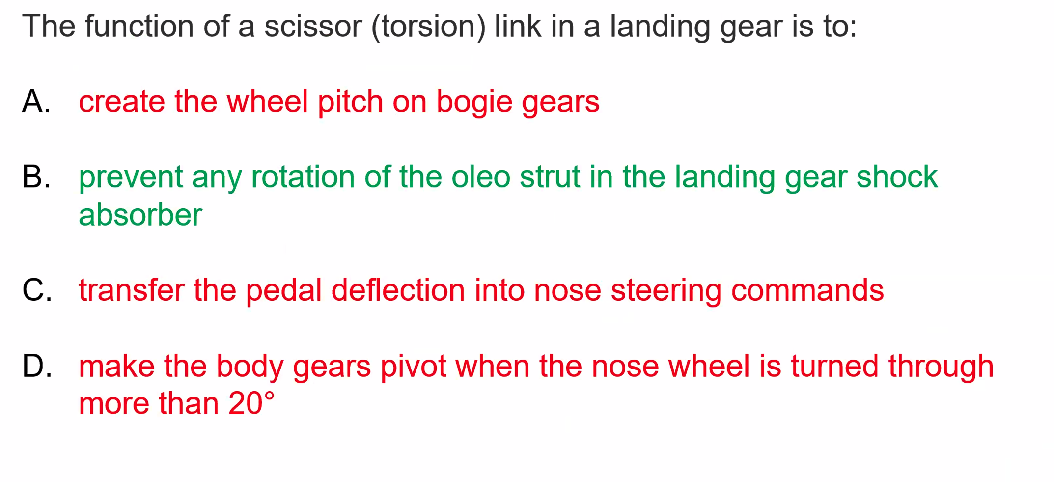
Chosen design depends on anticipated weight that wheel / oleo will need to absorb. The one thing they all have in common is the torque links to enable the oleo to move up and down.
The torque links can also be used to enable steering on the wheel.
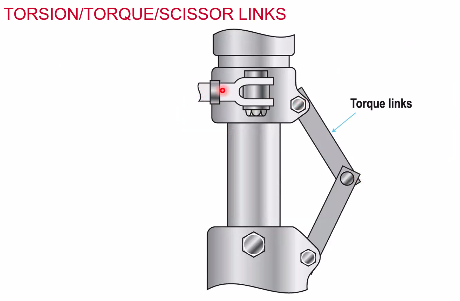
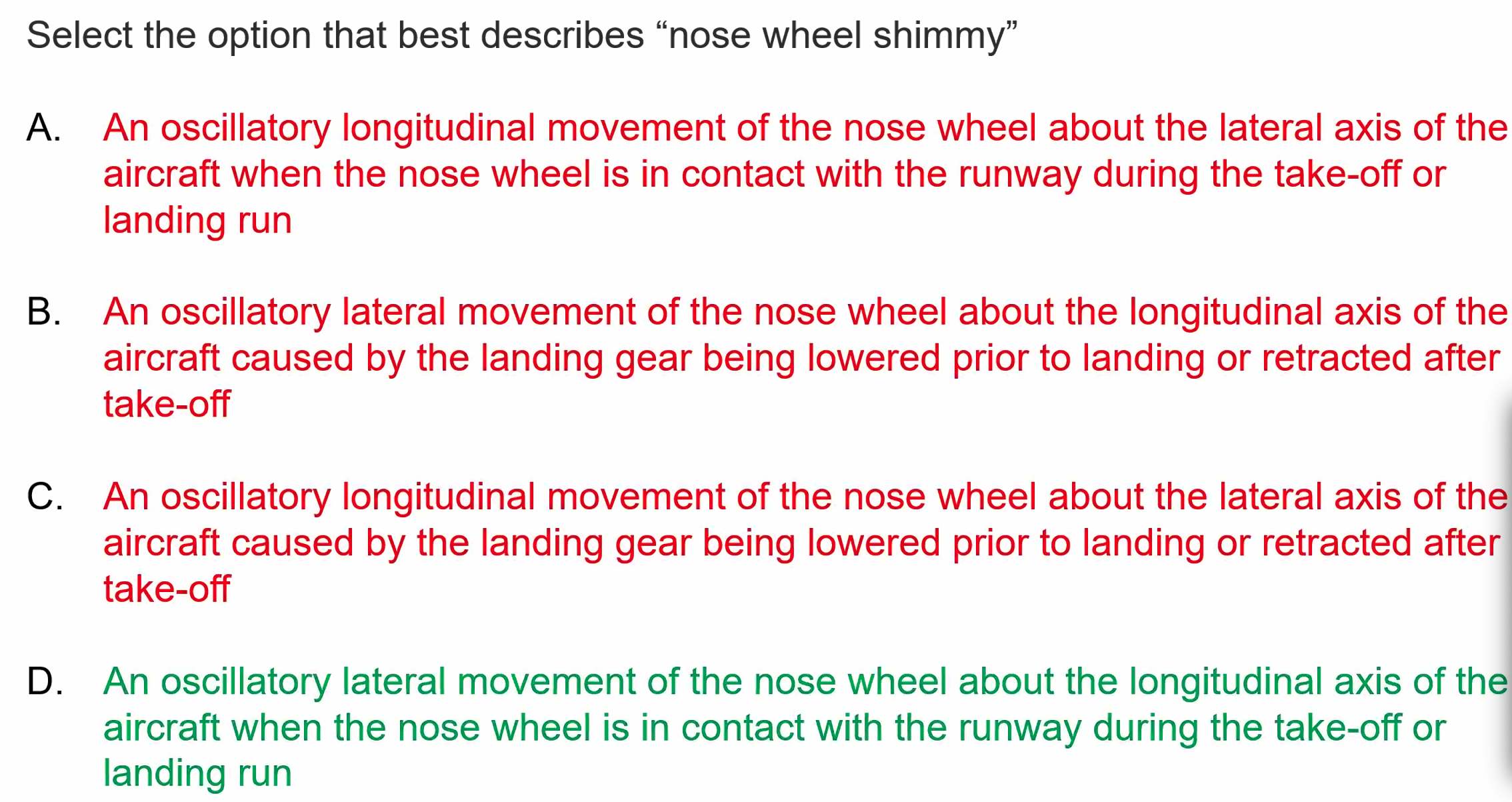
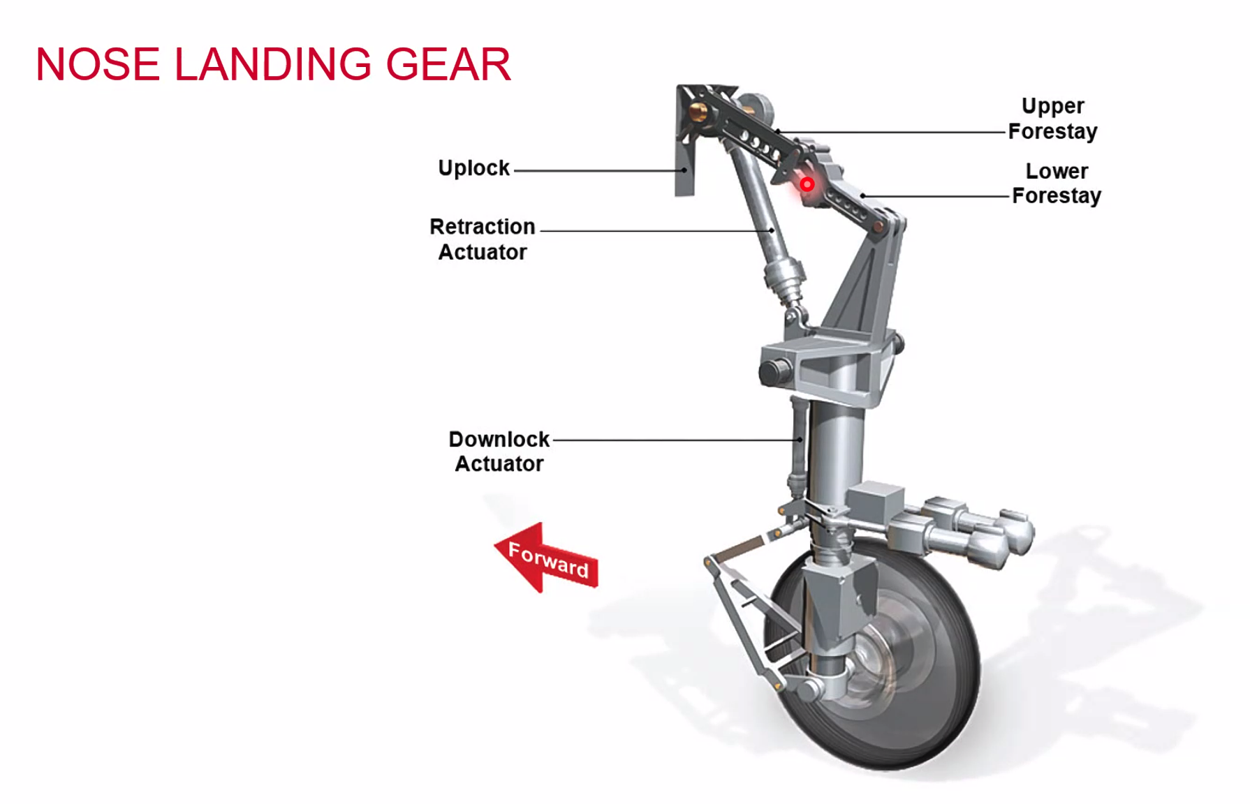
Where the red dot is can be used for steering actuators OR for a shimmy damper.
Oleo Pneumatic Shock Strut
- Uses Gas
- Nitrogen to support weight and act as a spring
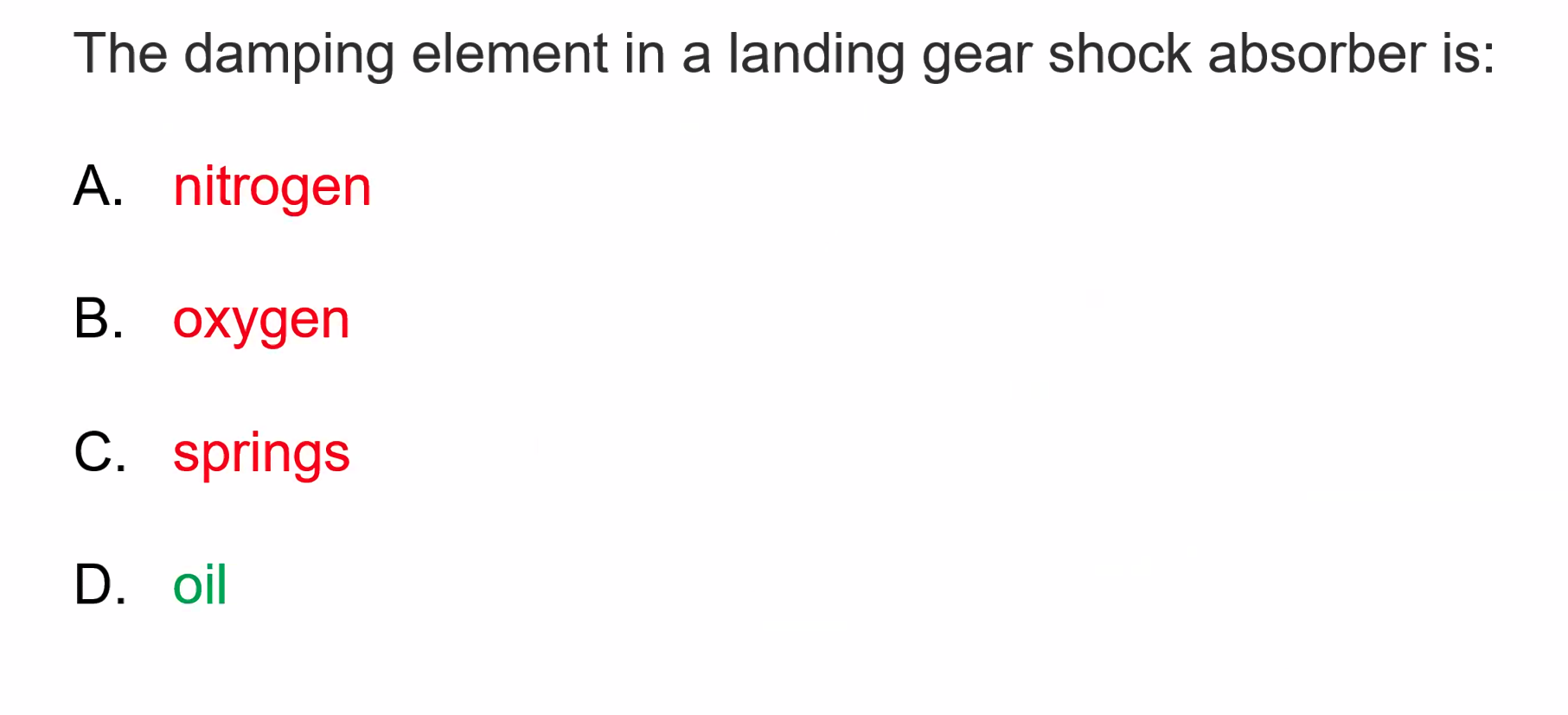
- Oil
- Uses hydraulic fluid, DTD585 which will dampen the load
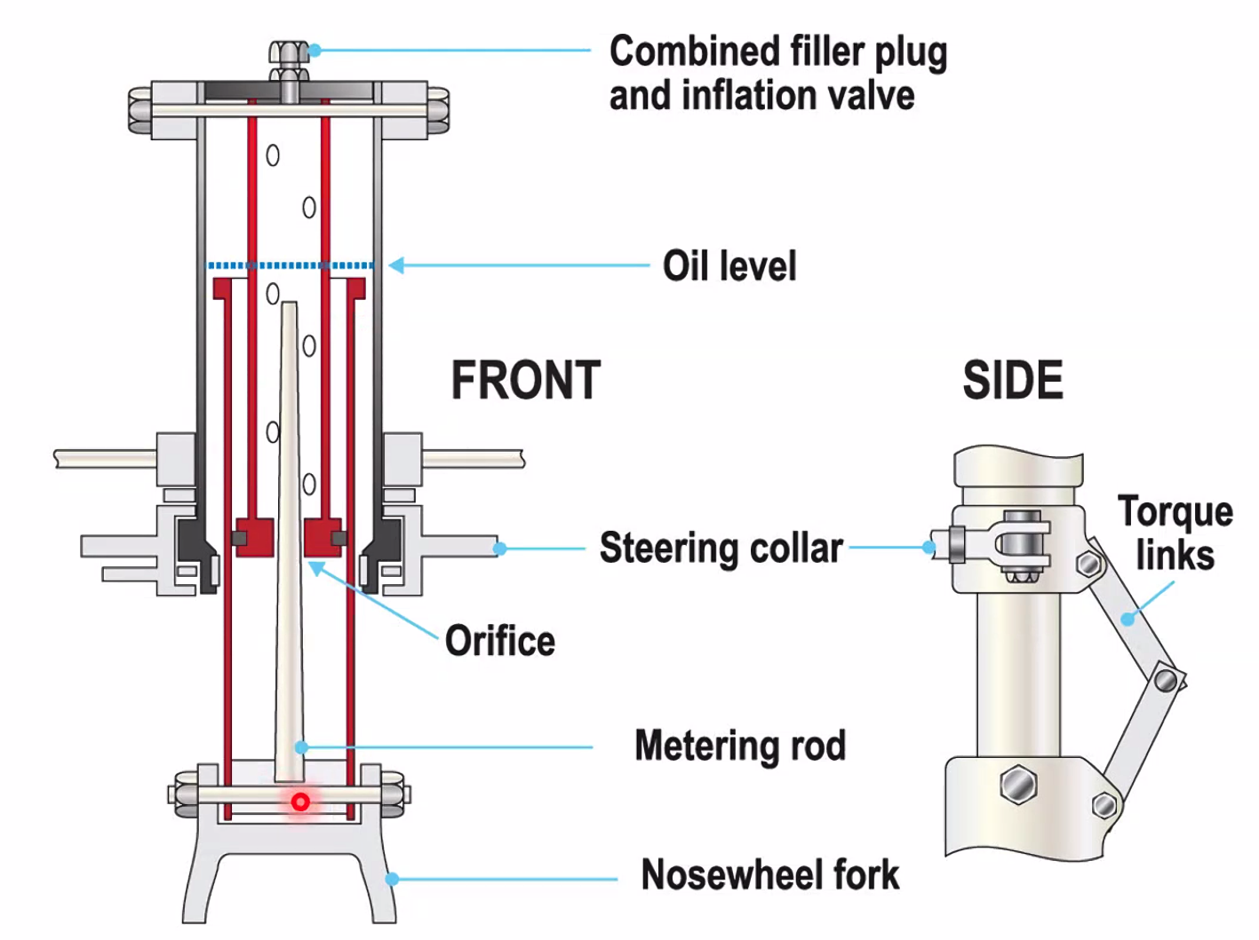
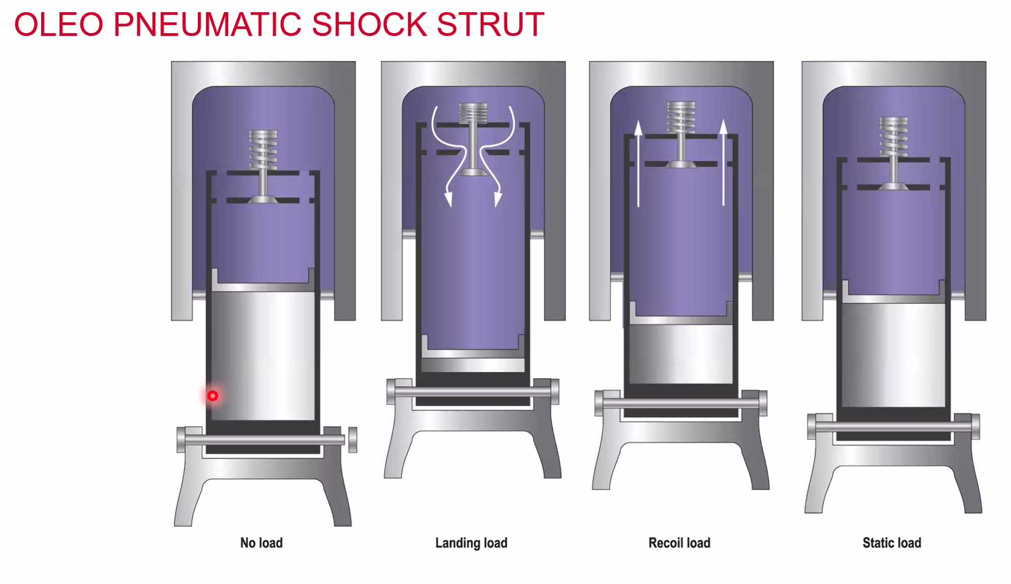
A modern version houses the air at the bottom and the hydraulic oil at the top. When landing it compresses the gas. The hydraulic oil will be allowed back into the main chamber through restrictors to prevent rapid expansion
Retraction and Extensions
- VLO - Maximum speed to operate the landing gear
- VLE - Maximum speed with the gear extended
Difference is due to the doors of the gear. To prevent collapse / retraction we have ground locking pins - red flags that need to be removed before flight.
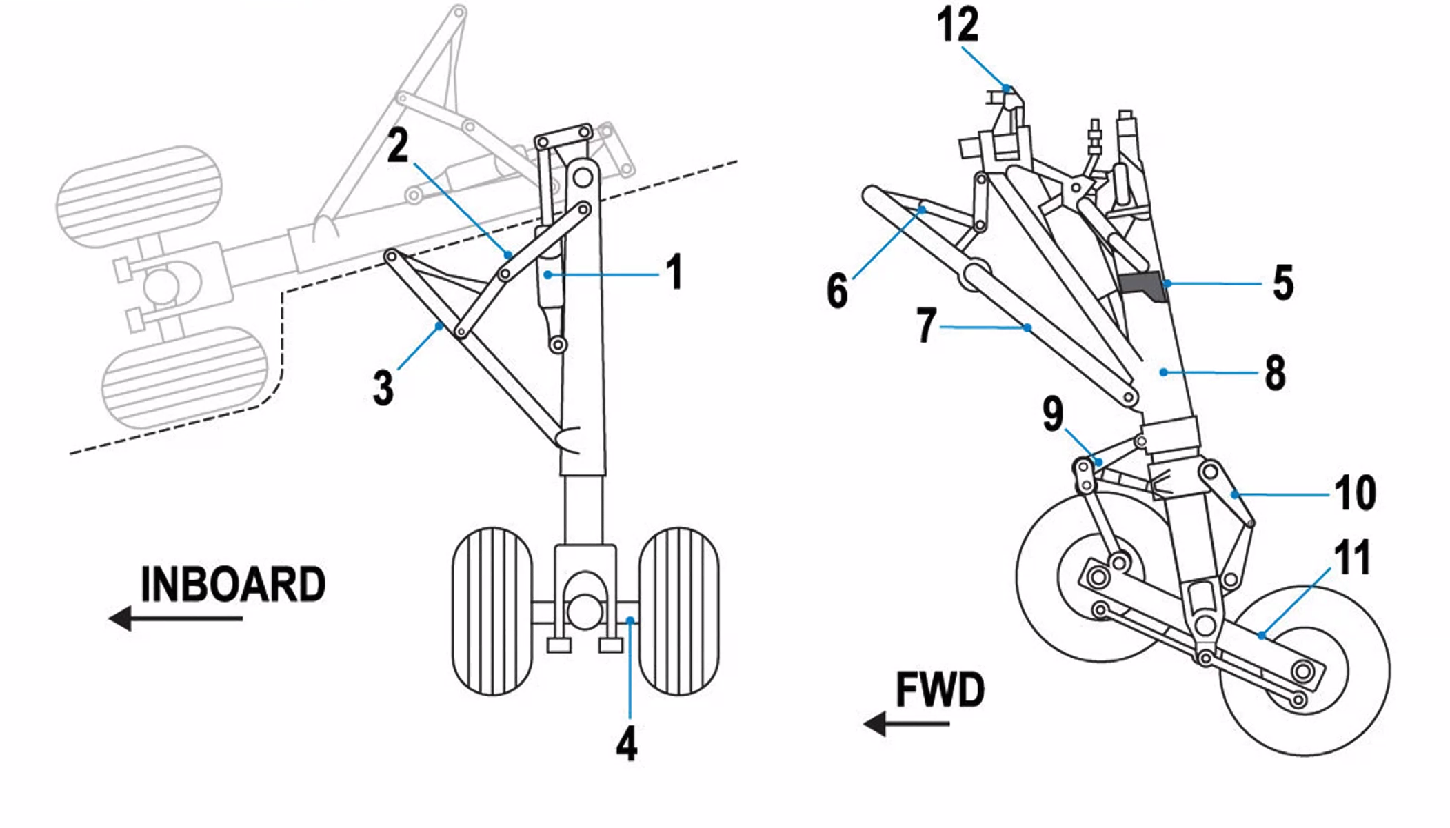
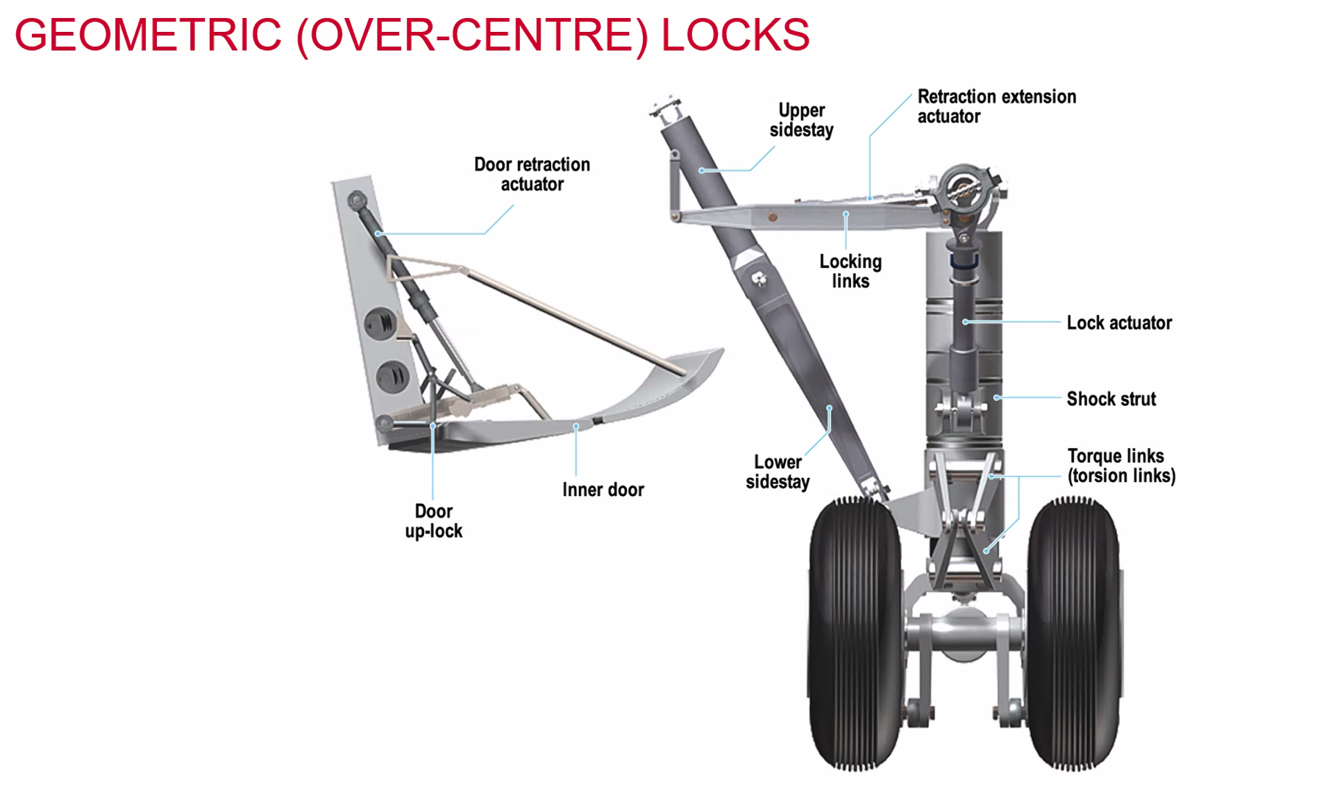
- Actuating / Retracting Cylinder
- Downlock Strut
- Sidestay
- Axle
- Piston
- Downlock Strut
- Brace Strut
- Oleo
- Hydraulic Strut
- Torque Link
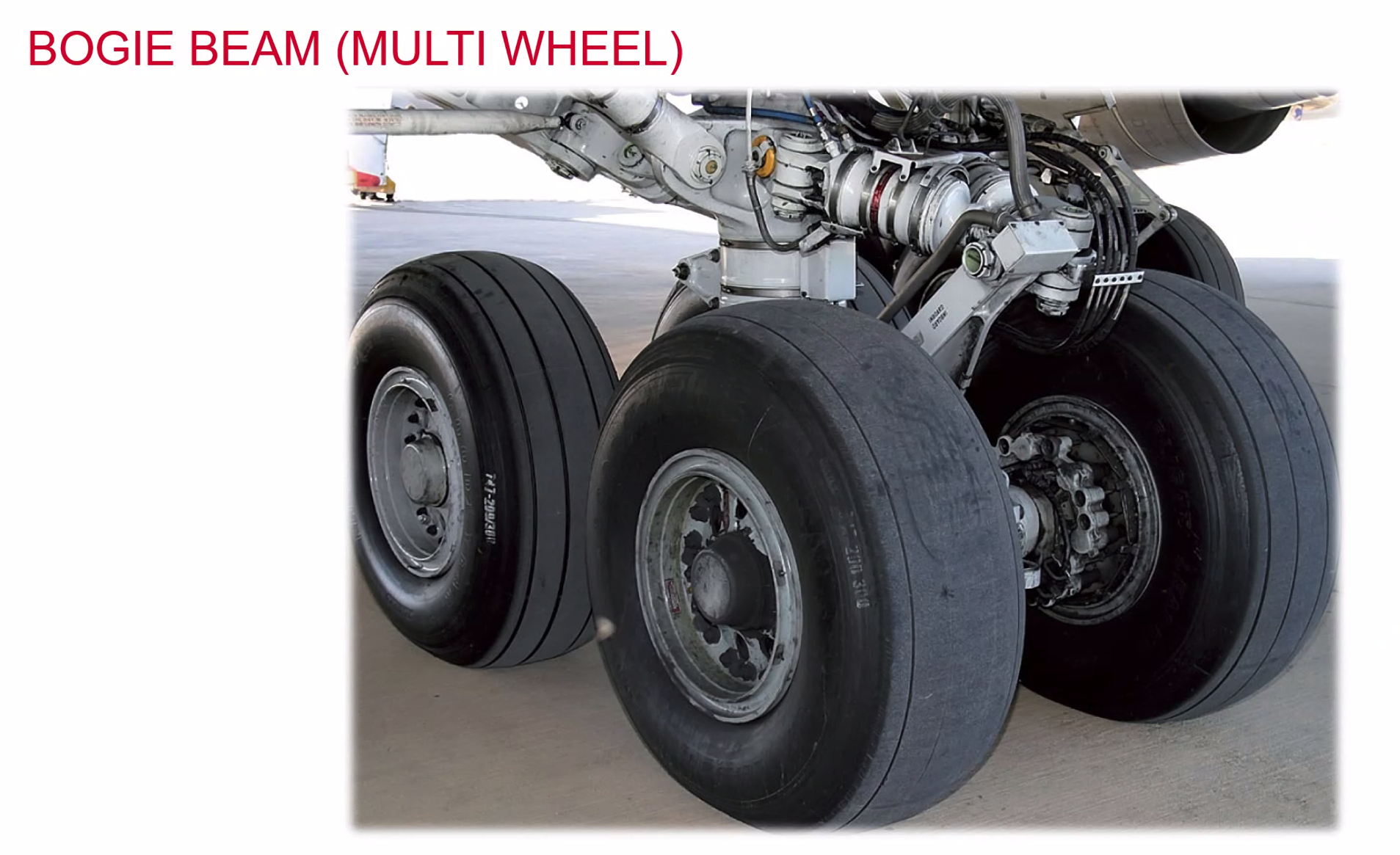
- Bogie Beam
- Mounting Lug
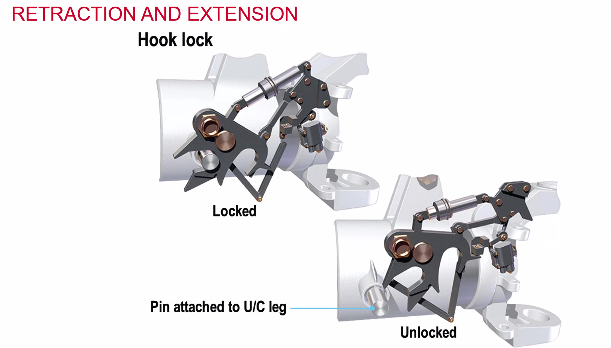 Similar design principle to a garden gate lock. It hooks around the Pin attached to a U/C leg.
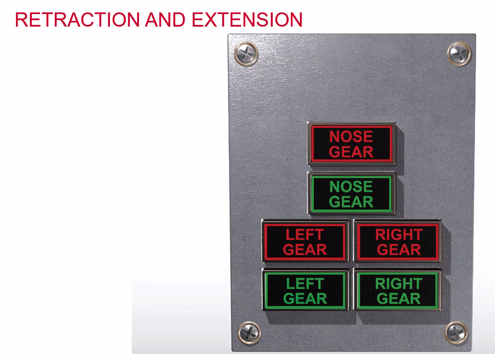
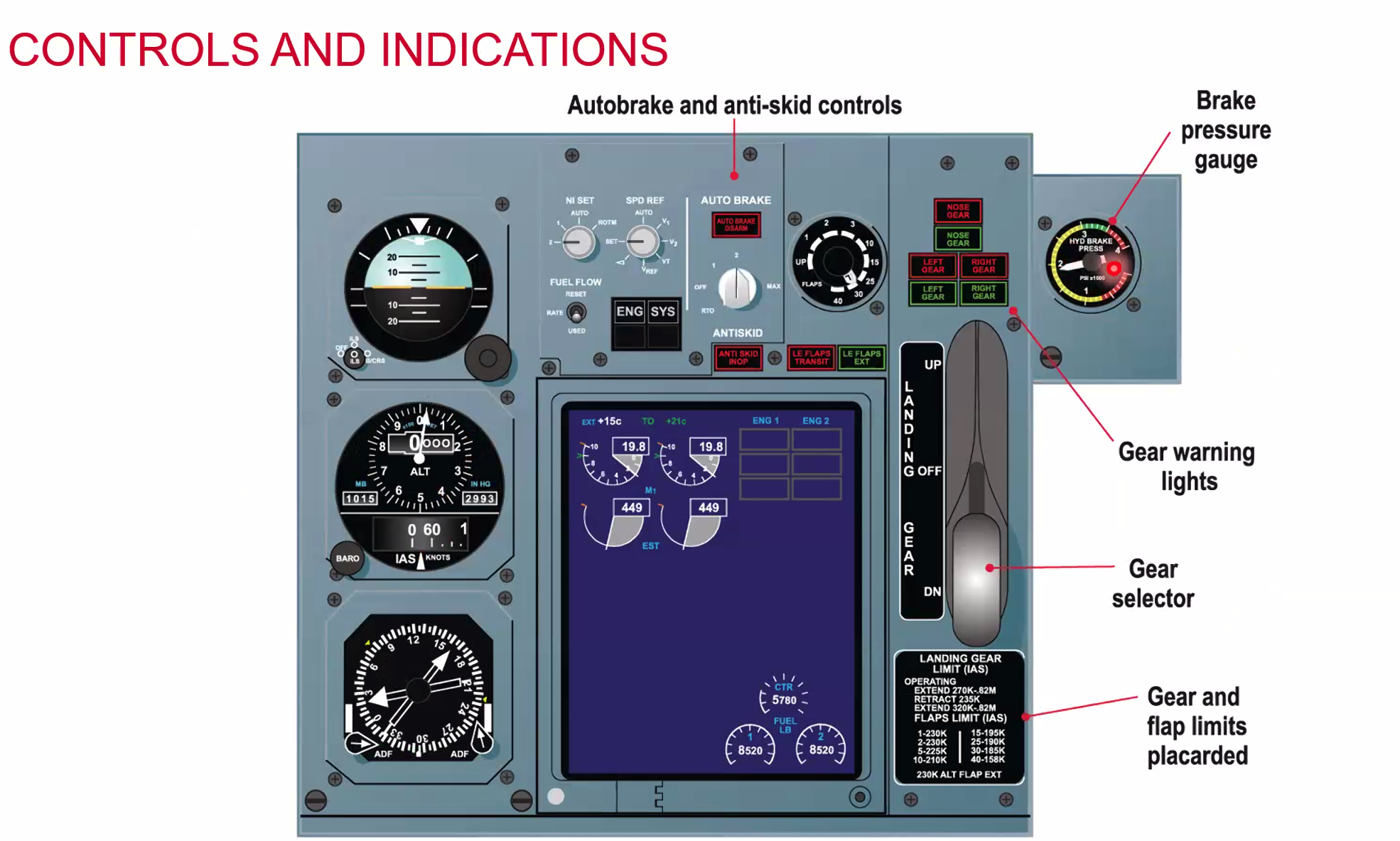
3 Green - down and locked any discrepancy would show red or orange. Red and Green will show that its been lowered by emergency means
Can also have warning lights for Door, In Trans and Truck
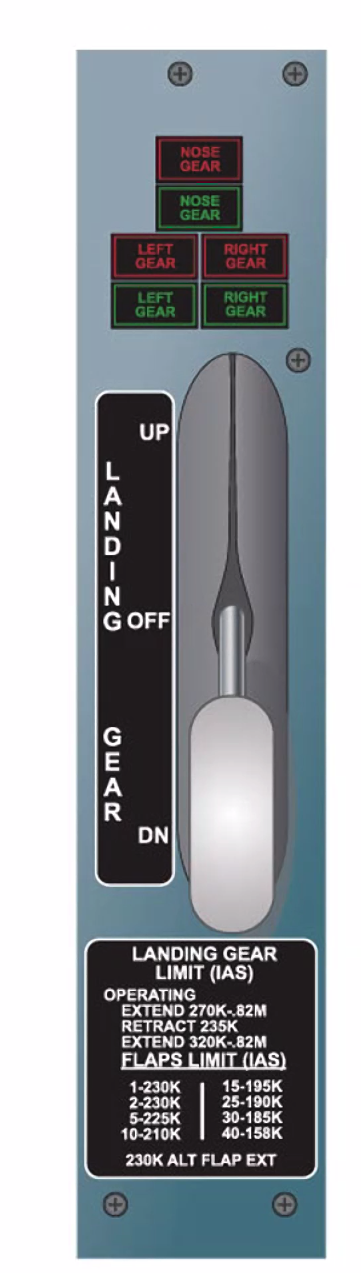
Landing gear control panel
- must be wheel shaped and has a mechanical interlock - must be pulled out and then up/down.
- Up to raise the gear, down to lower the gear.
- The panel is disabled when the weight on wheels electrical interlock is activated.
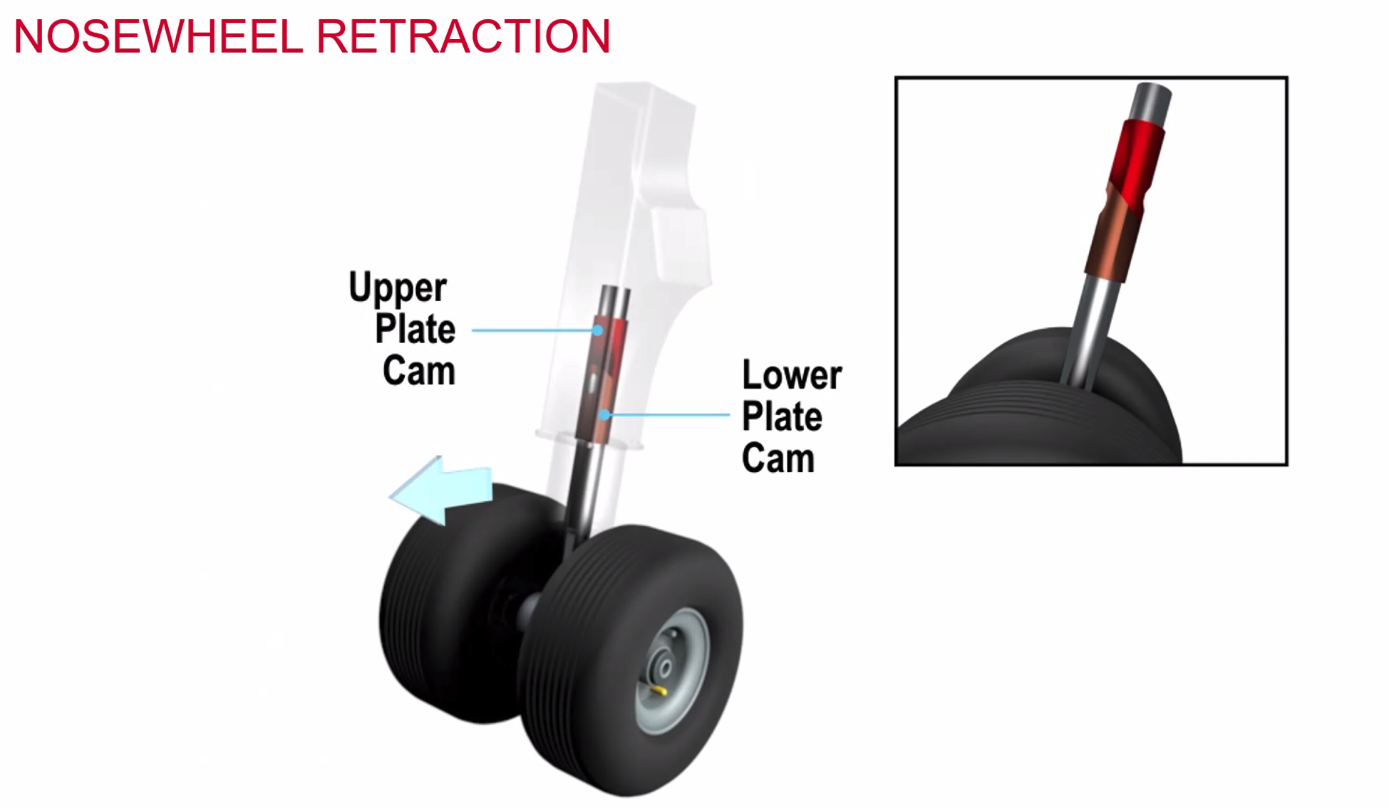 Notice the difference in the angle of the red/copper sections. As the nose gear is retracted the wheel will rotate to fit in the wheel bay.
Steering
In light aircraft most of it is done with differential braking with a castoring nose wheel. On larger aircraft completed with a tiller or hand wheel. Rudder pedal nose wheel.
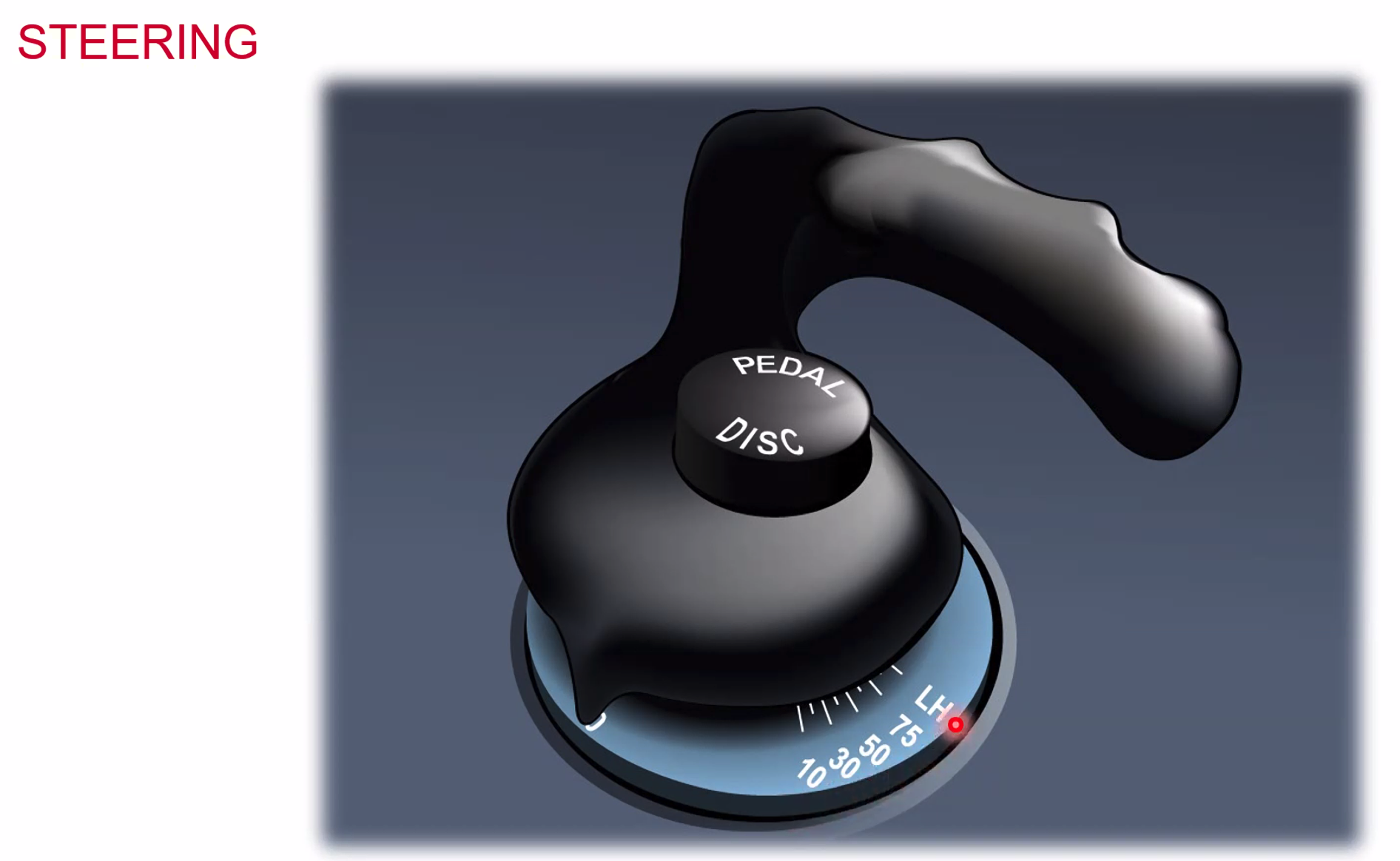
The Pedal Disc, disconnects the link from rudder to nose wheel steering.
Brakes
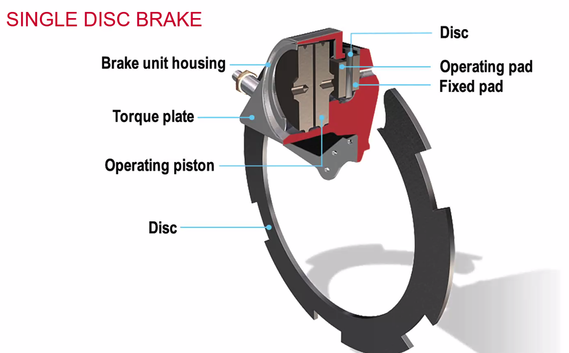
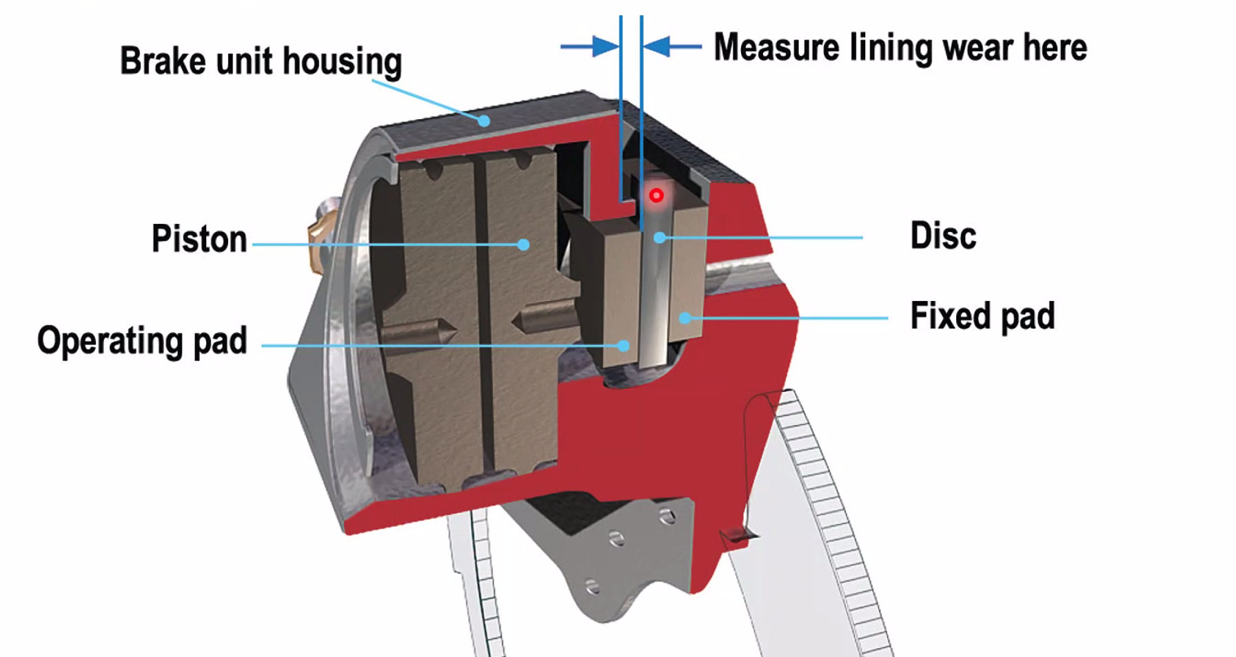
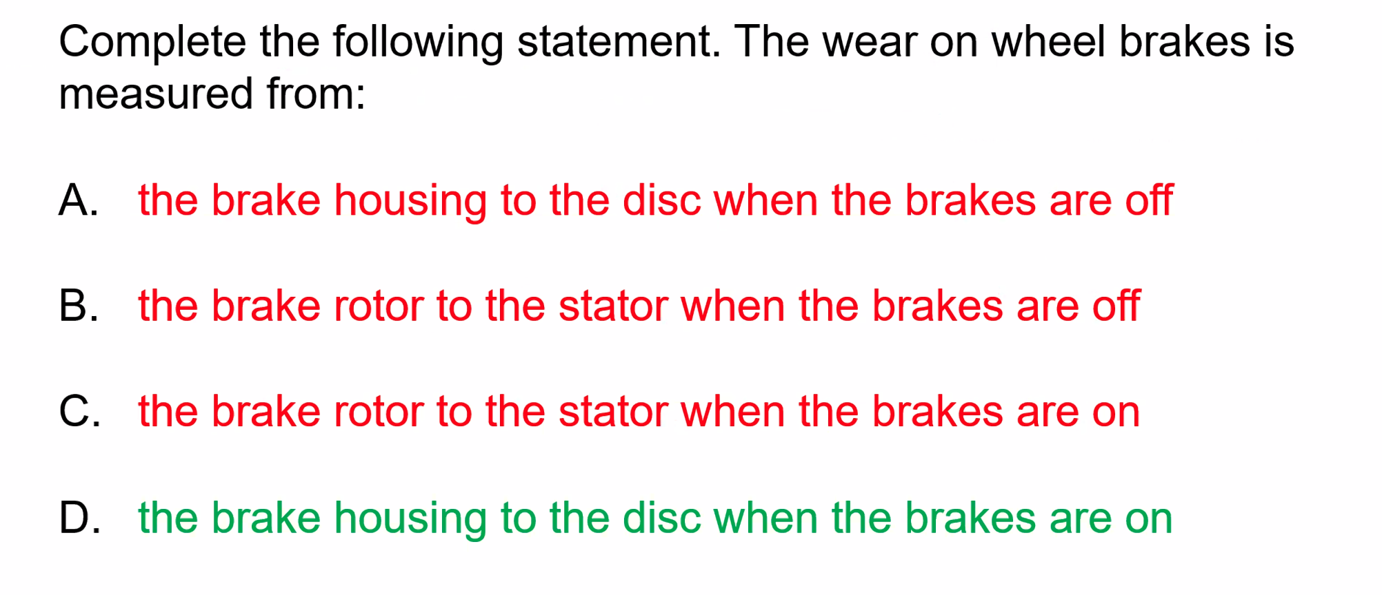
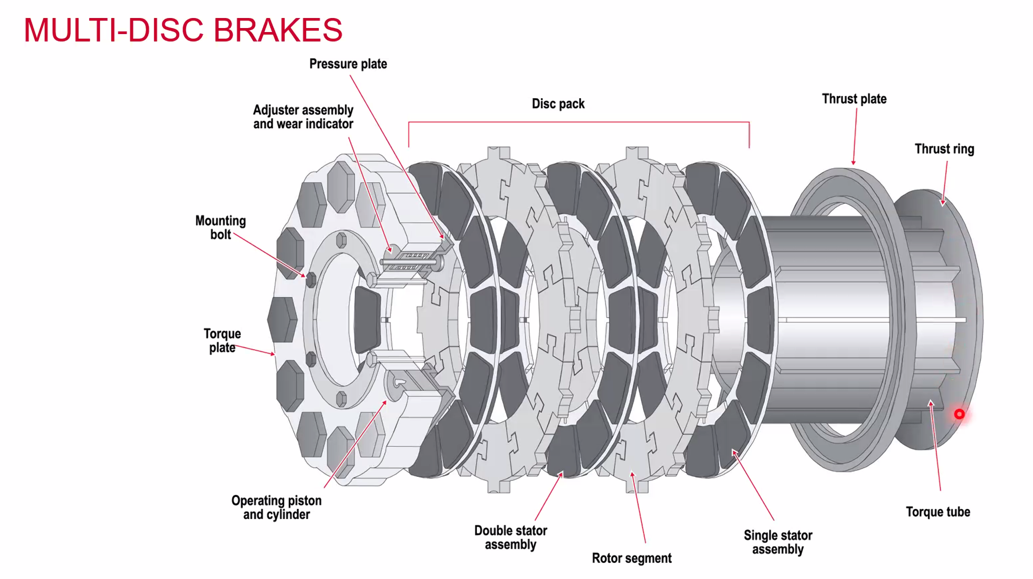
Newer disc brakes are made from carbon brakes (rather than steel) to save weight. On a 777 switching from steel to carbon saves 800kgs.
Anti skid systems
- Braking applies torque to wheel to oppose rotation
- too much - wheel locks, skid developers
- not enough - insufficient braking action
- Anti skid designed for all conditions
- Used for every take off and landing
- two main types
- Mechanical (Dunlop Maxarat)
- Electrical
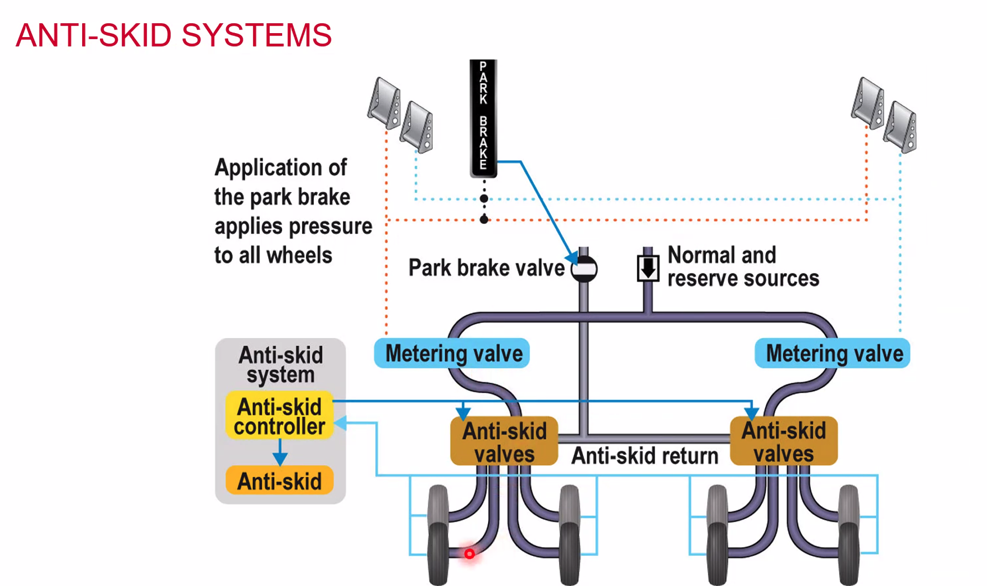
Mechanical Anti Skid Systems (Maxaret)
- Hydro-mechanical system, wheel speed mechanically sensed
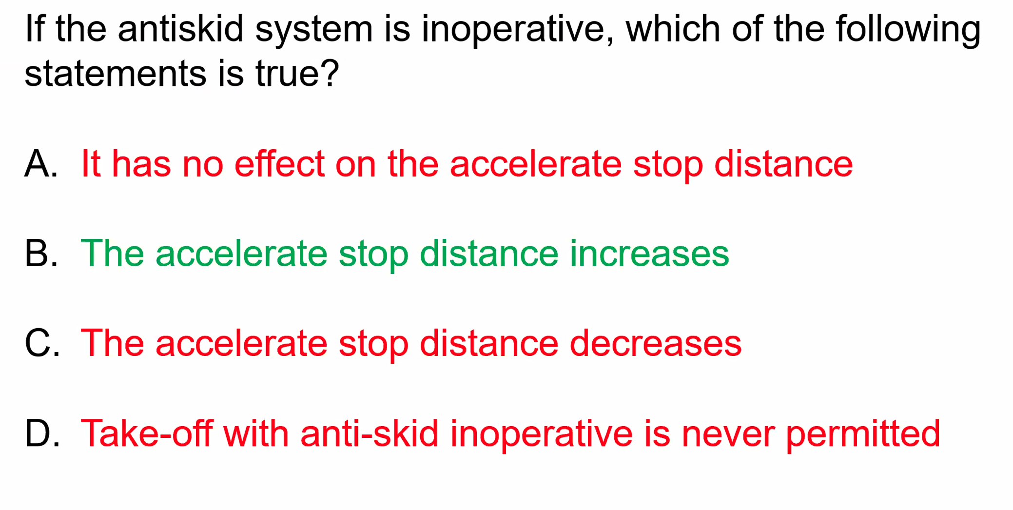
Electronic Anti Skid System
- Tacho generator driven by wheels, a signal is sent to the anti-skid controller to compare the speeds and a signal is sent to slow the wheels. Reduces brake hydraulic pressure.
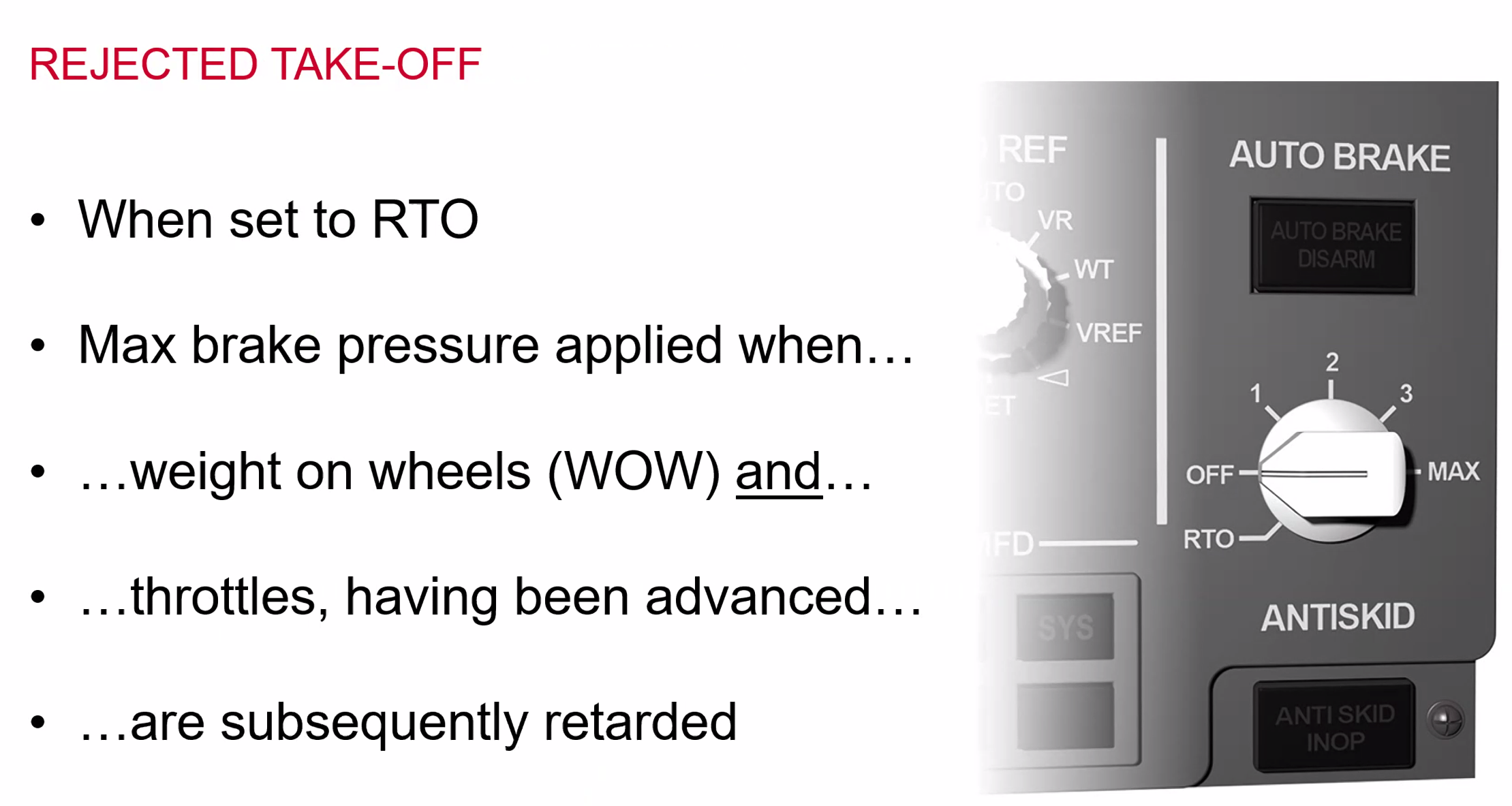
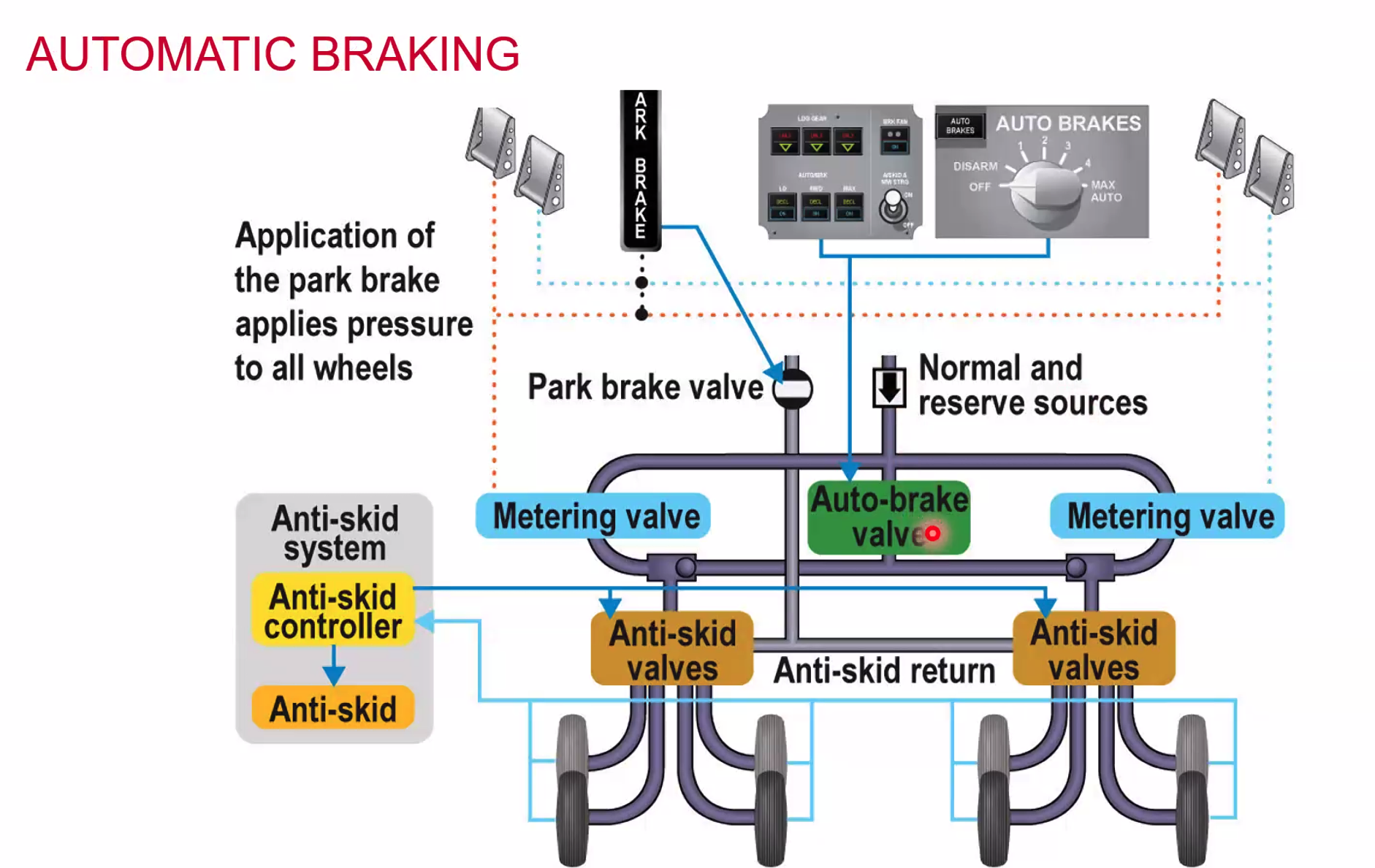
Automatic Braking
- constant rate of ‘g’ deceleration
- passenger comfort, reduces aircraft fatigue / stress
- Always used in conjunction with the Anti-skid systems
- Rate of deceleration selected by pilot
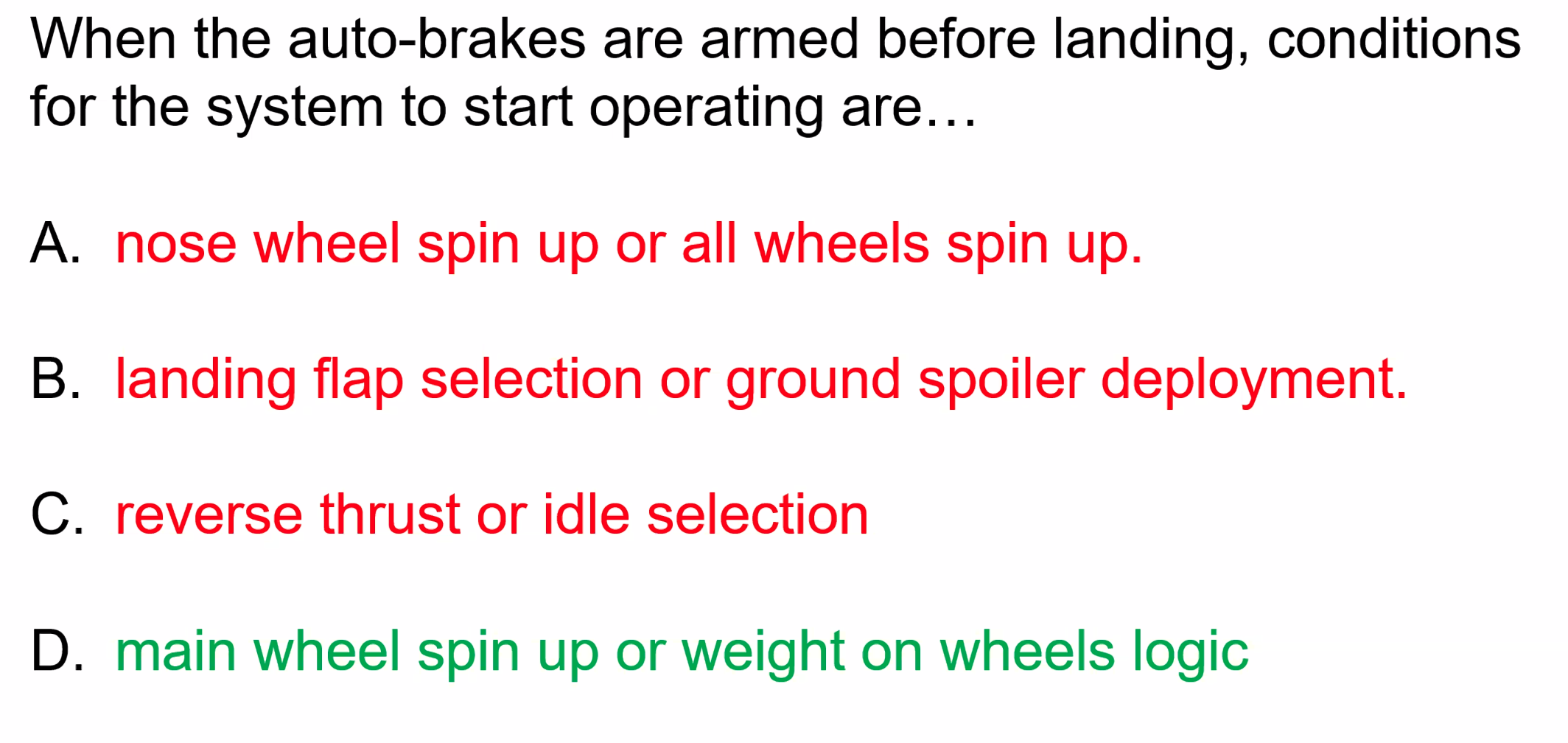
- On touchdown brakes automatically applied when
- throttles set to idle
- wheels spun up to speed
- Brake pressure modulated to achieve desired ‘g’
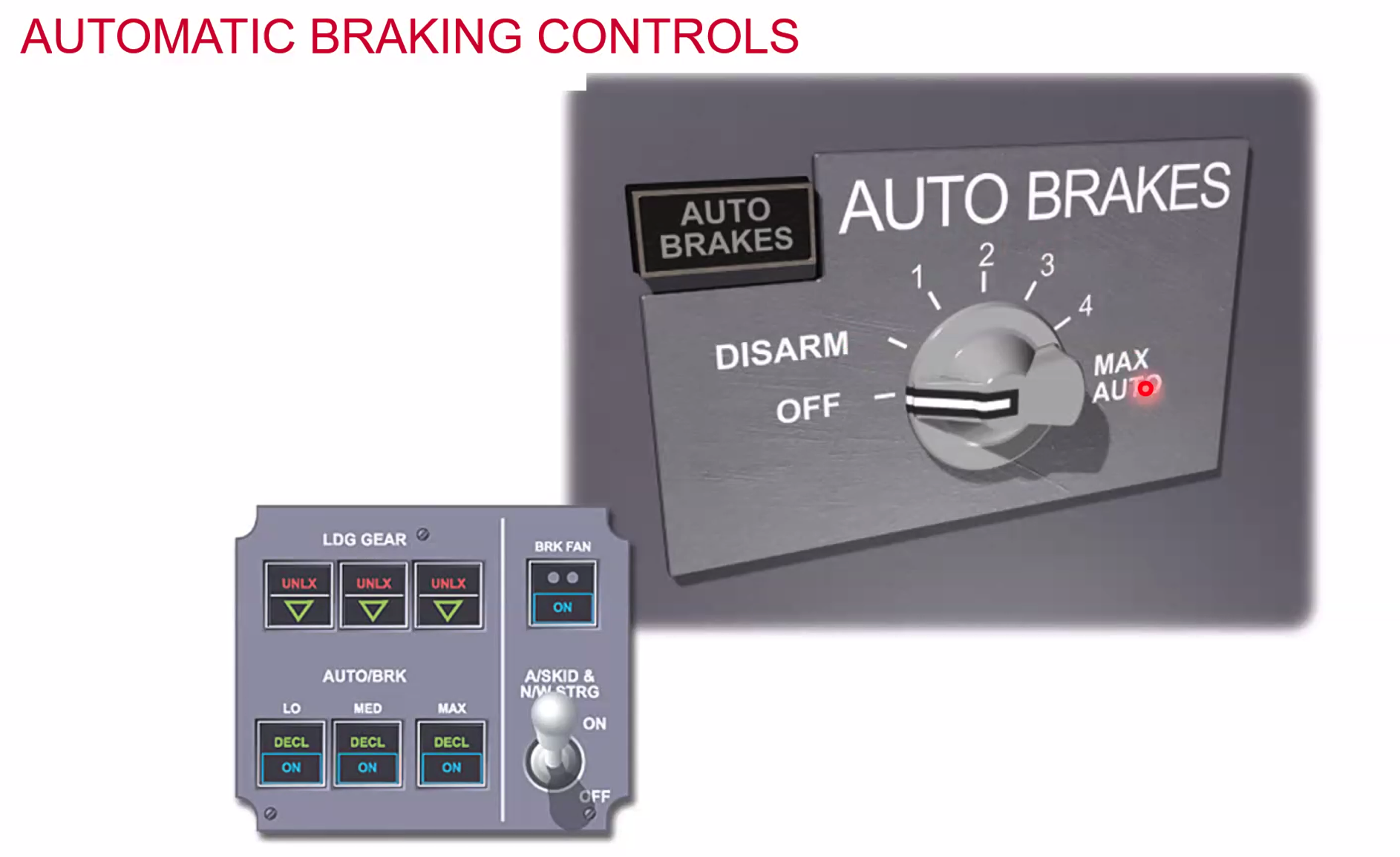
Airbus on the left, older Boeing on the right.
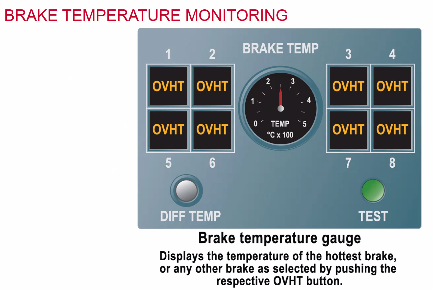
The inner dial defaults onto the highest temperature of one of the 8 brakes. Or you can select a brake to see the temp.
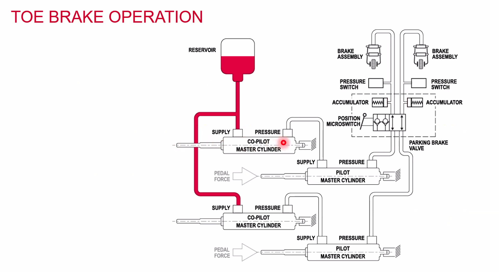
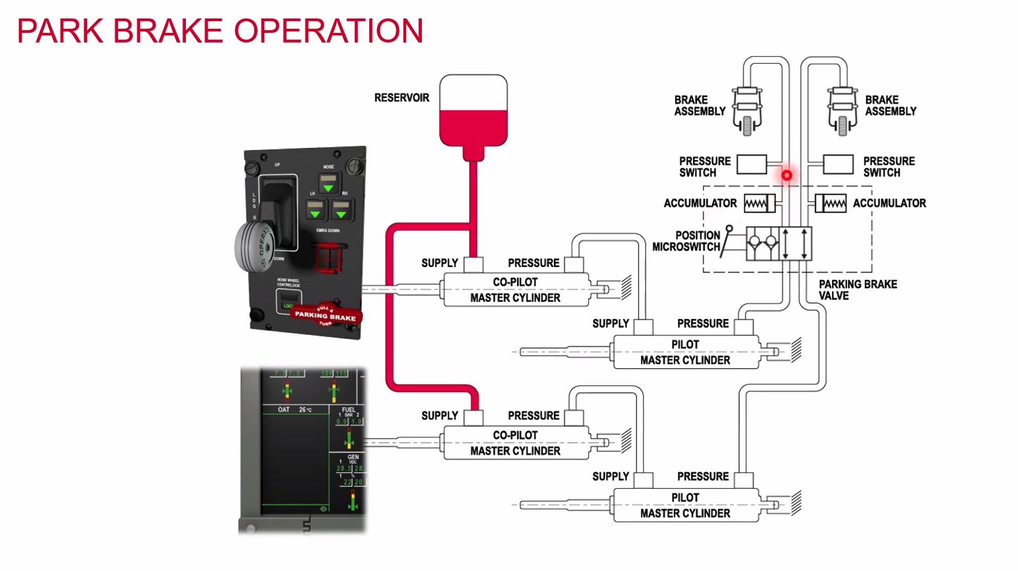
When the parking brake is applied the position/microswitch will ‘trap’ hydraulic pressure / fluid onto the brakes.
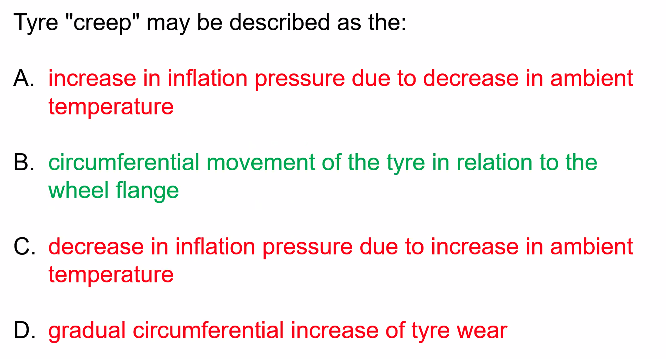
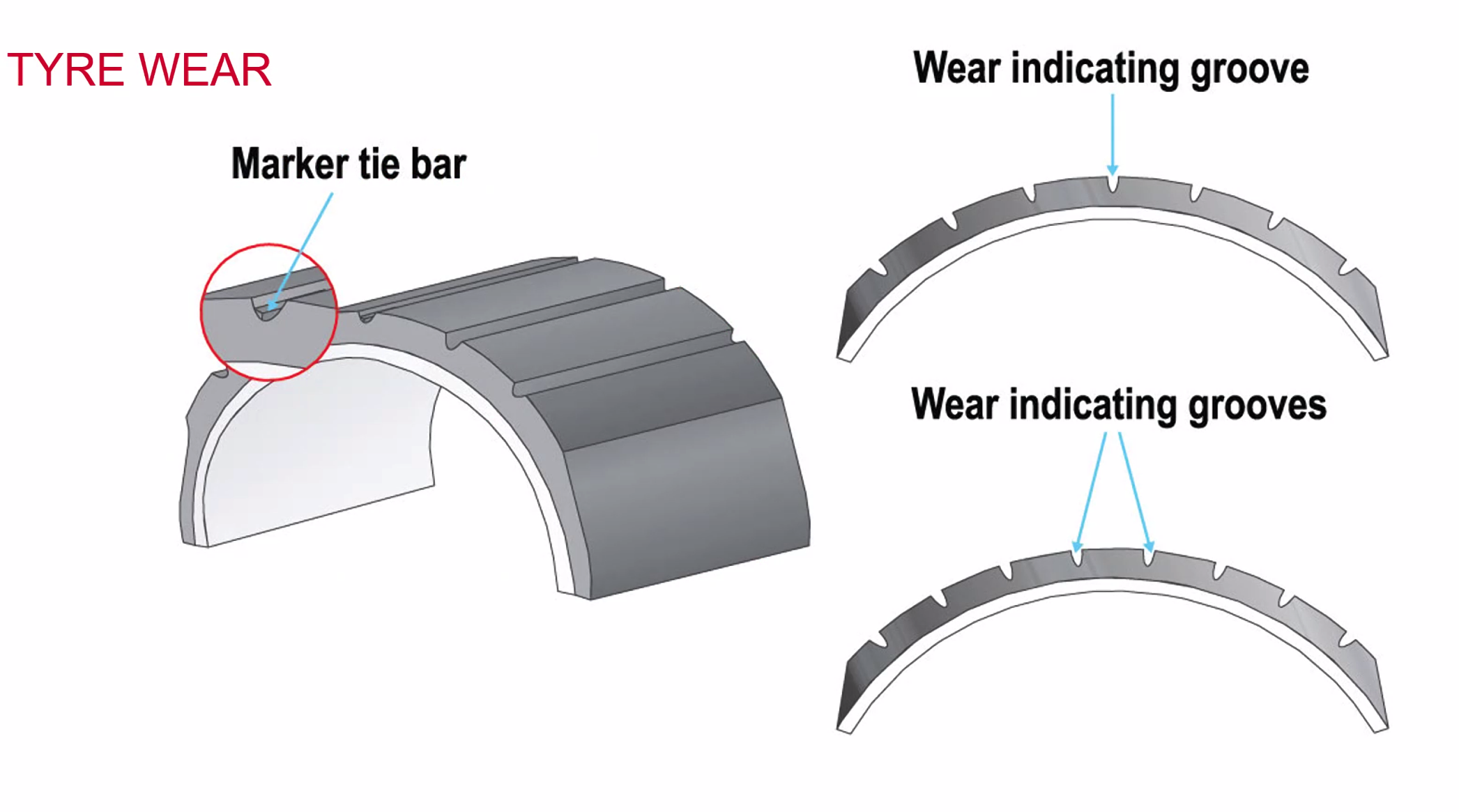
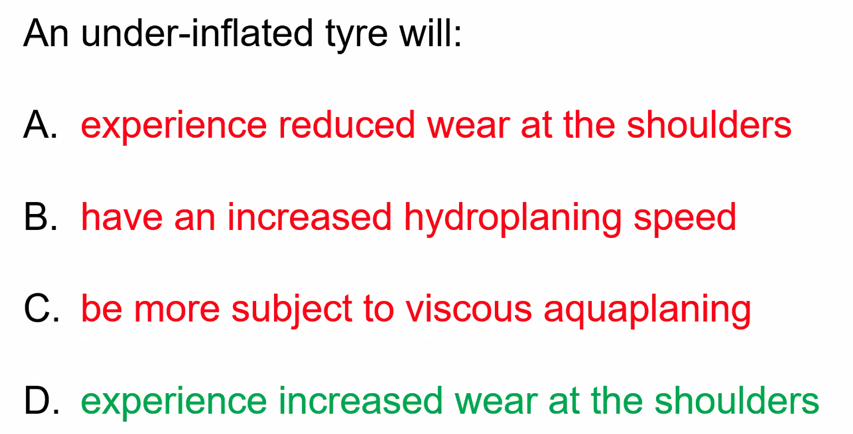
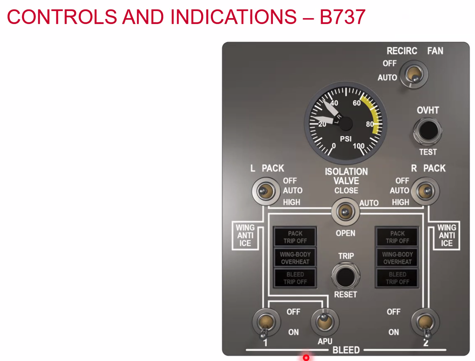
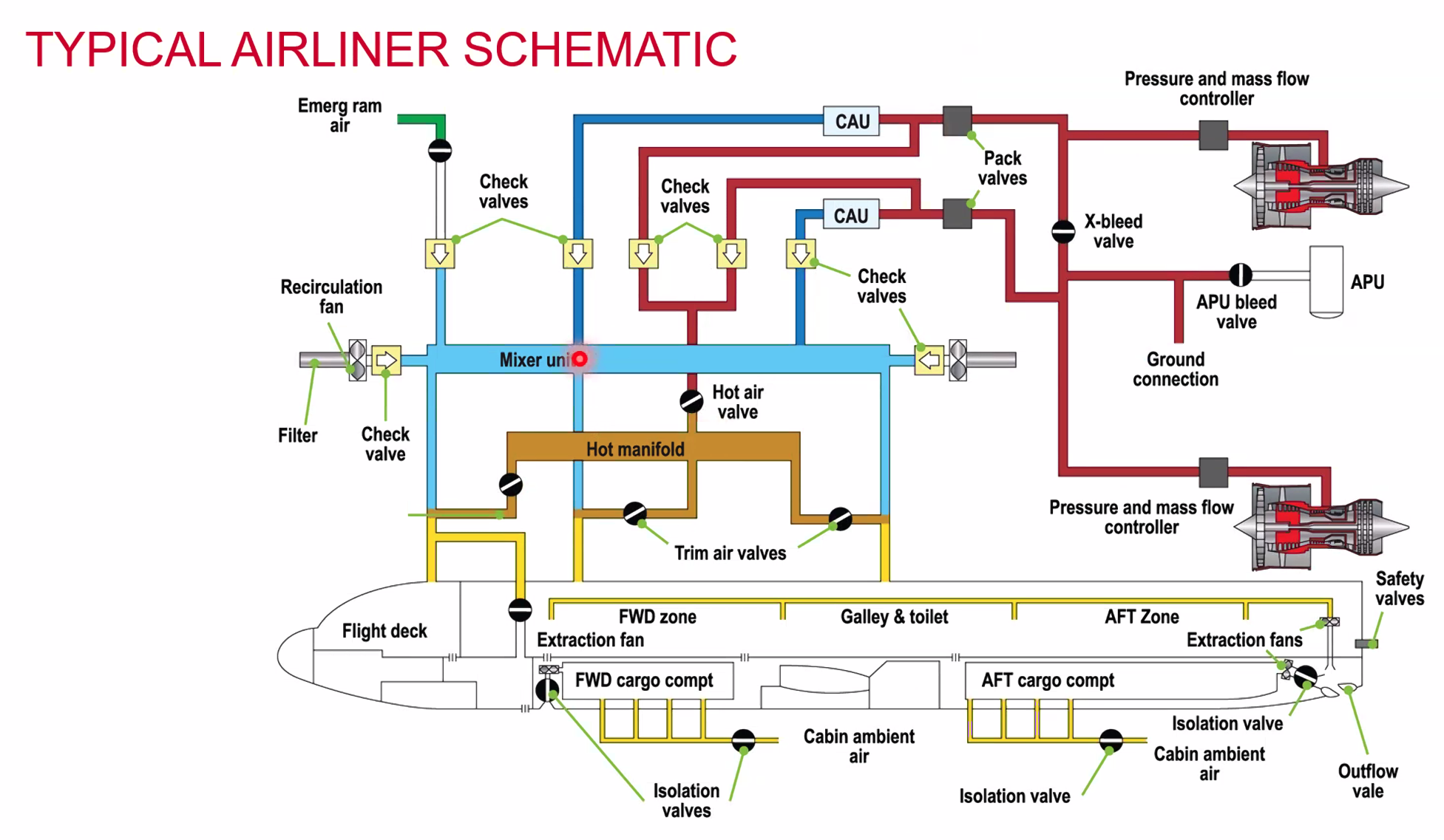
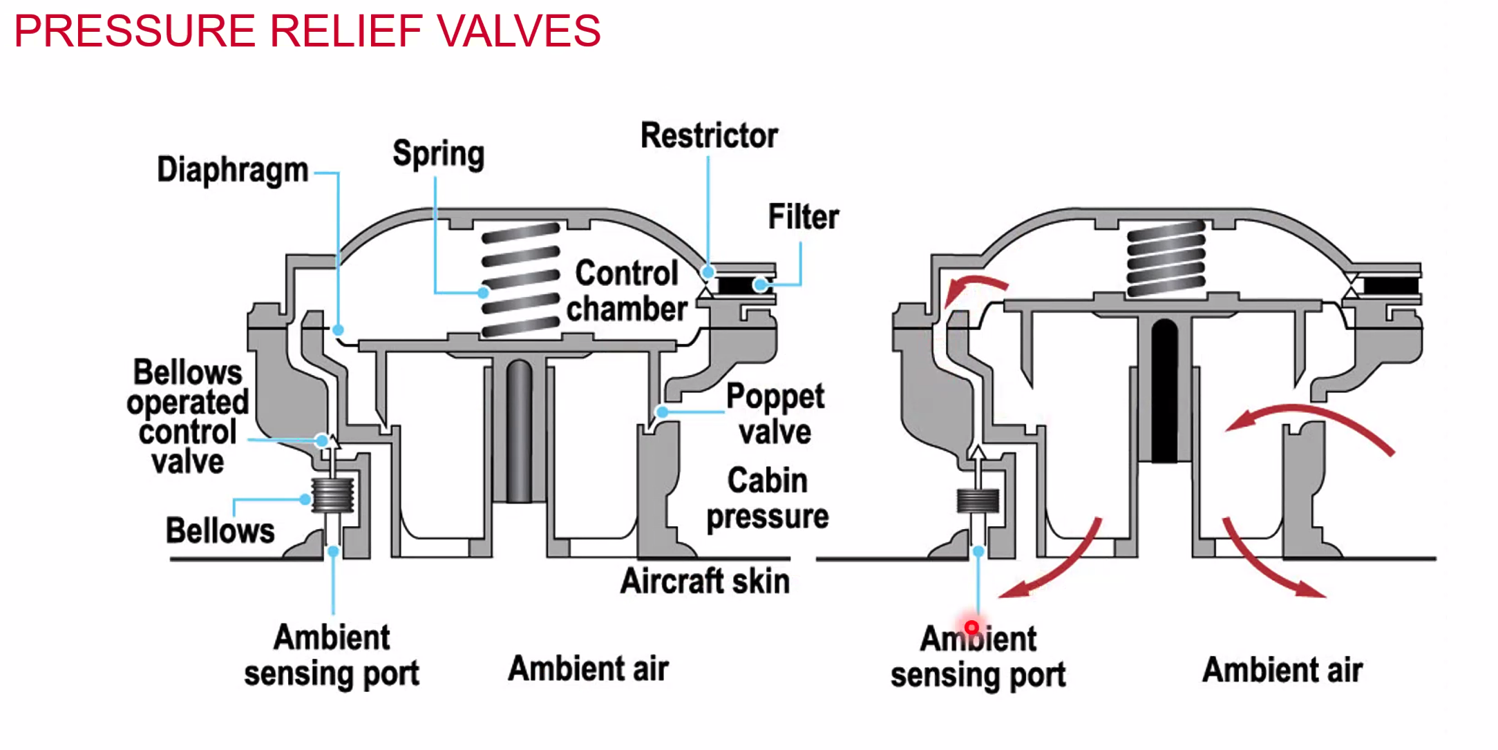
Air conditioning and pressurisations
Temperature Control
- large variations in temperature, OAT at height -60C, OAT on the ground up to +45C
- temperature control system helps to cope with the extremes and maintain a comfortable cabin environment
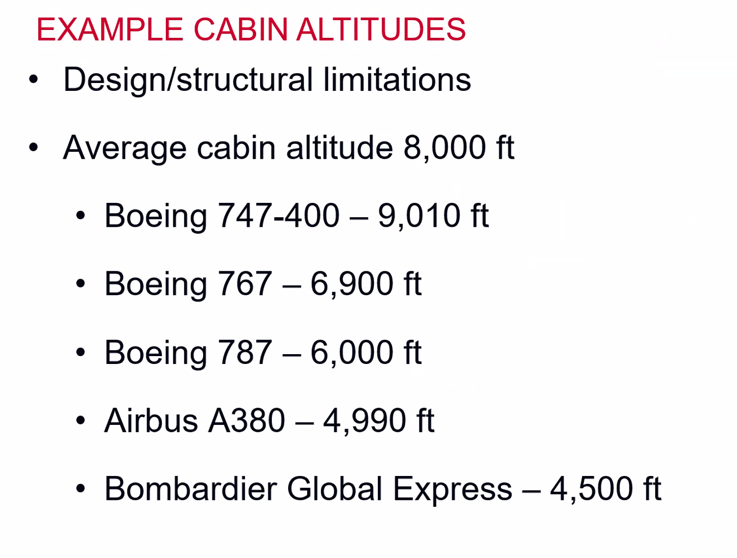
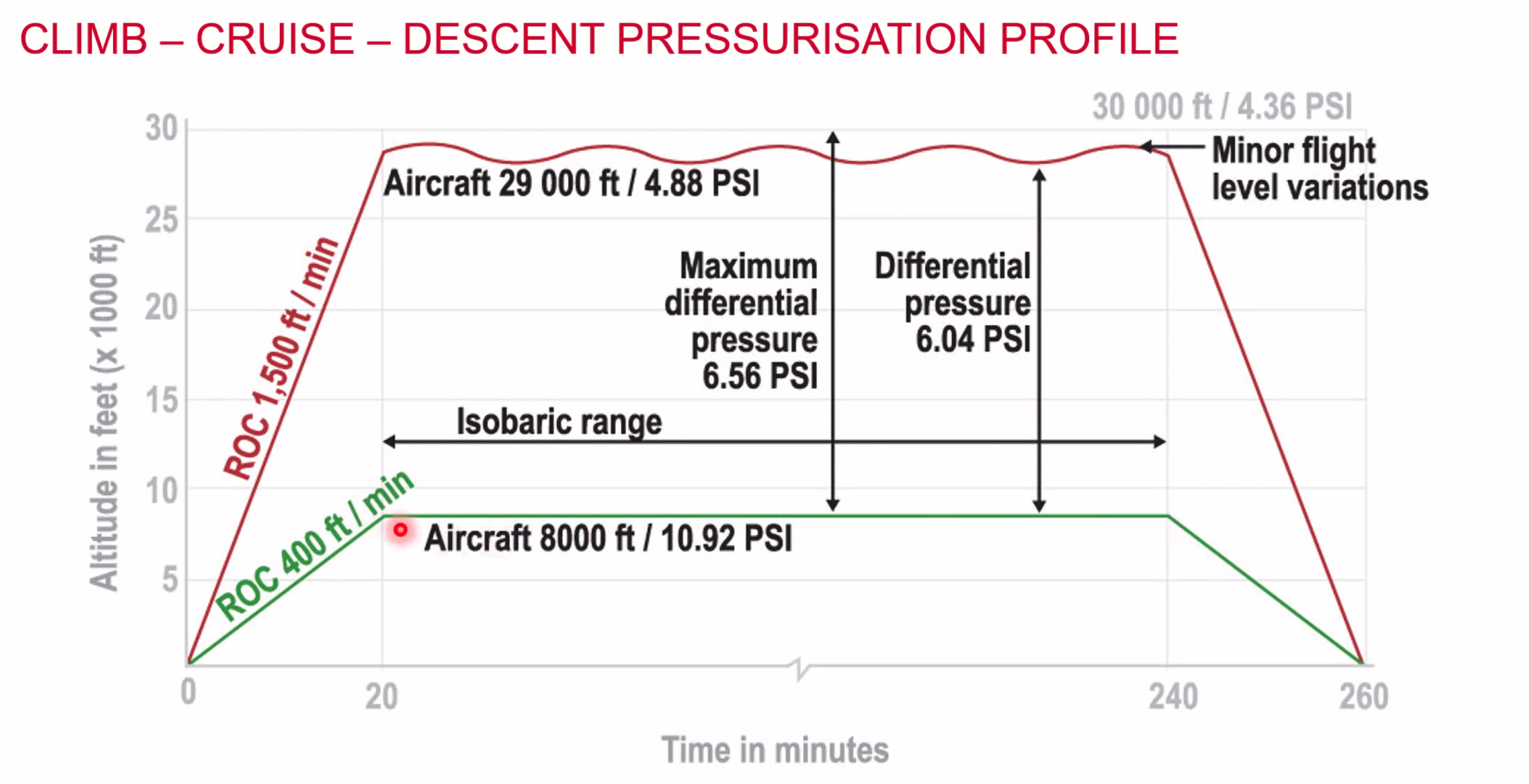
Pressure Regulation
- Atmosphere consists of 21% Oxygen, 78% Nitrogen, 1% other gases
- At altitude the density decreases, pressure decreases and temperature decreases
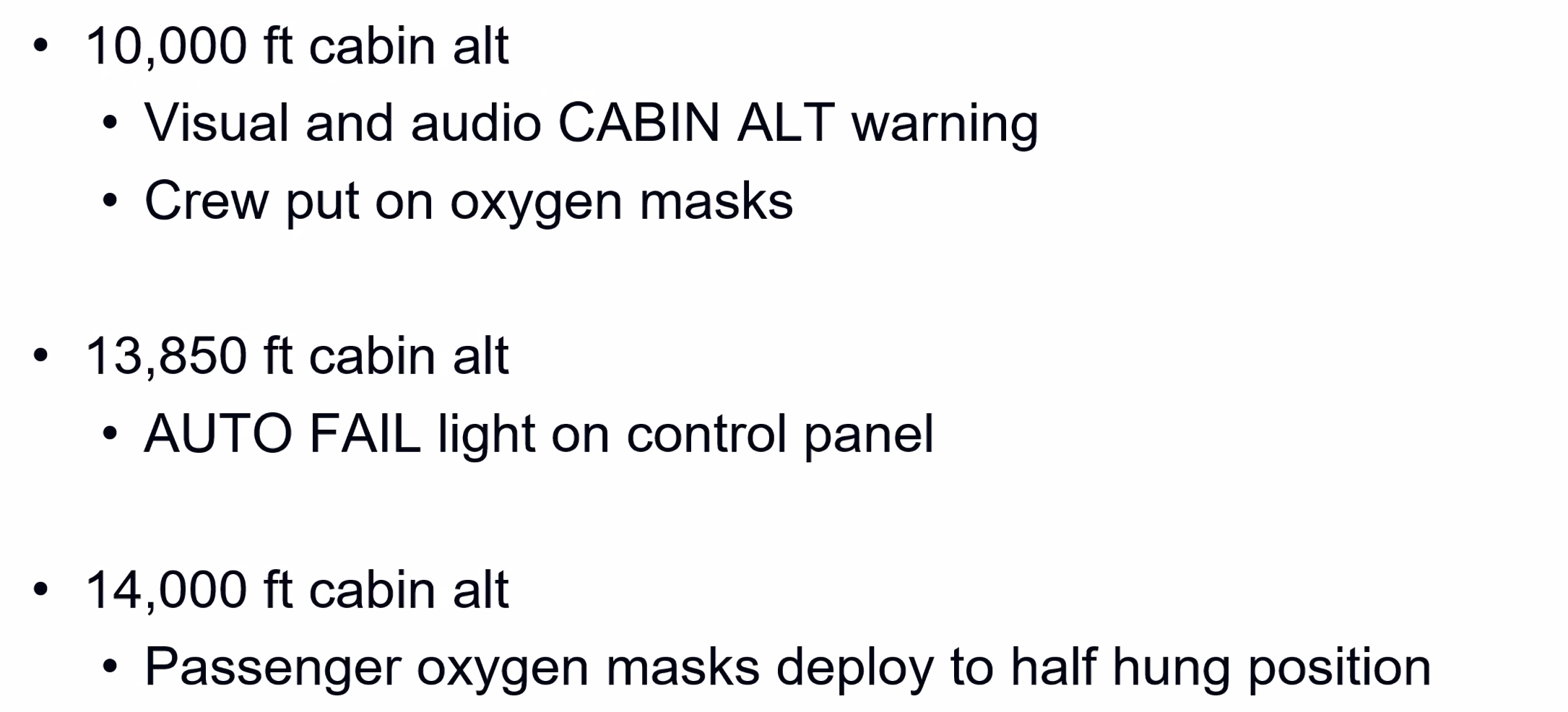
Above 10,000ft insufficient pressure results in Hypoxia. (Not Annoxia - which is the total lack of oxygen).
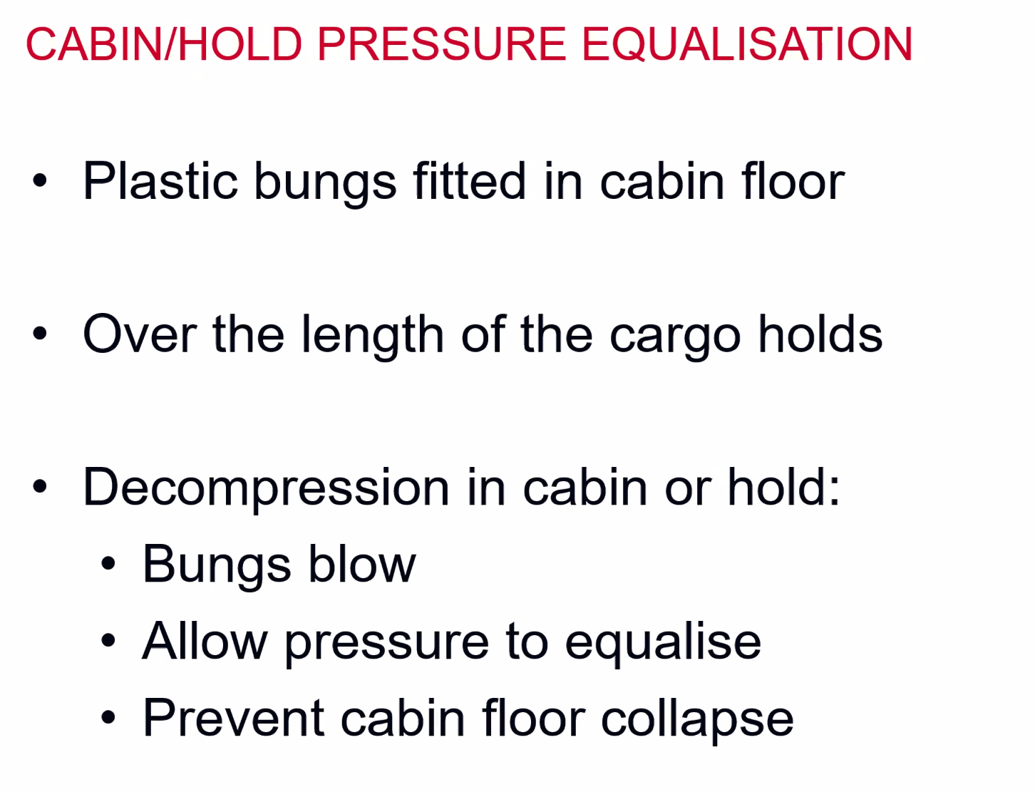
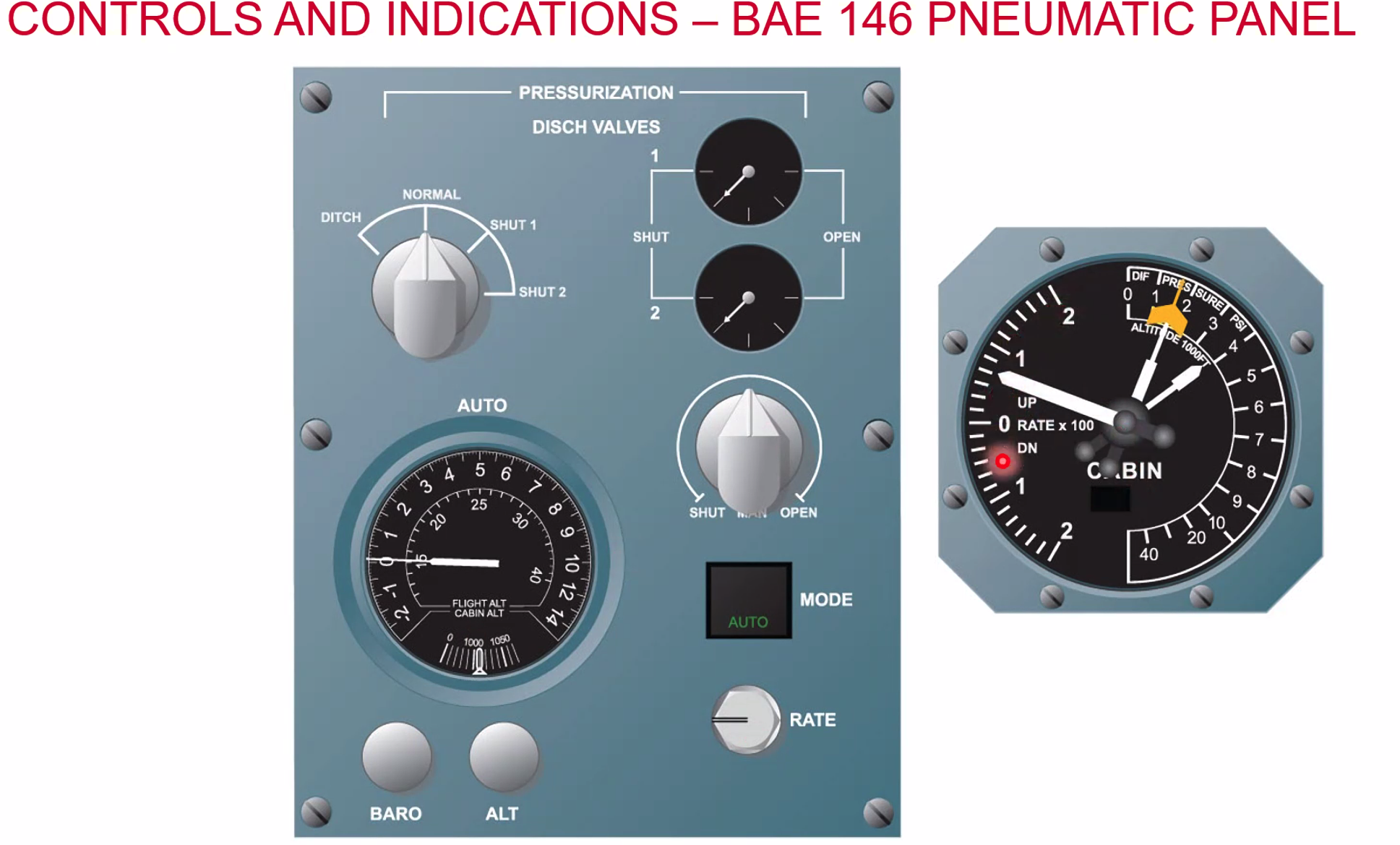
Aircraft are pressurised to allow for normal breathing.
Cooling Air cooled by:
- Heat exchanger - need large temp difference
- Making the air work
- Expansion
- Combined
Various Methods:
- Air cycle
- Boot strap
- Brake Turbine
- Turbofan
- Vapour Cycle
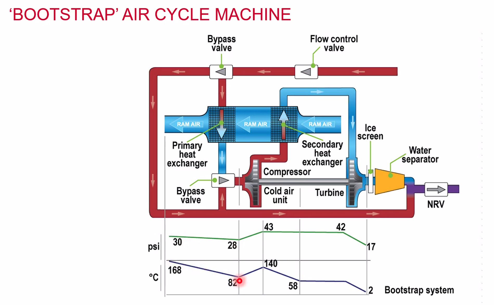
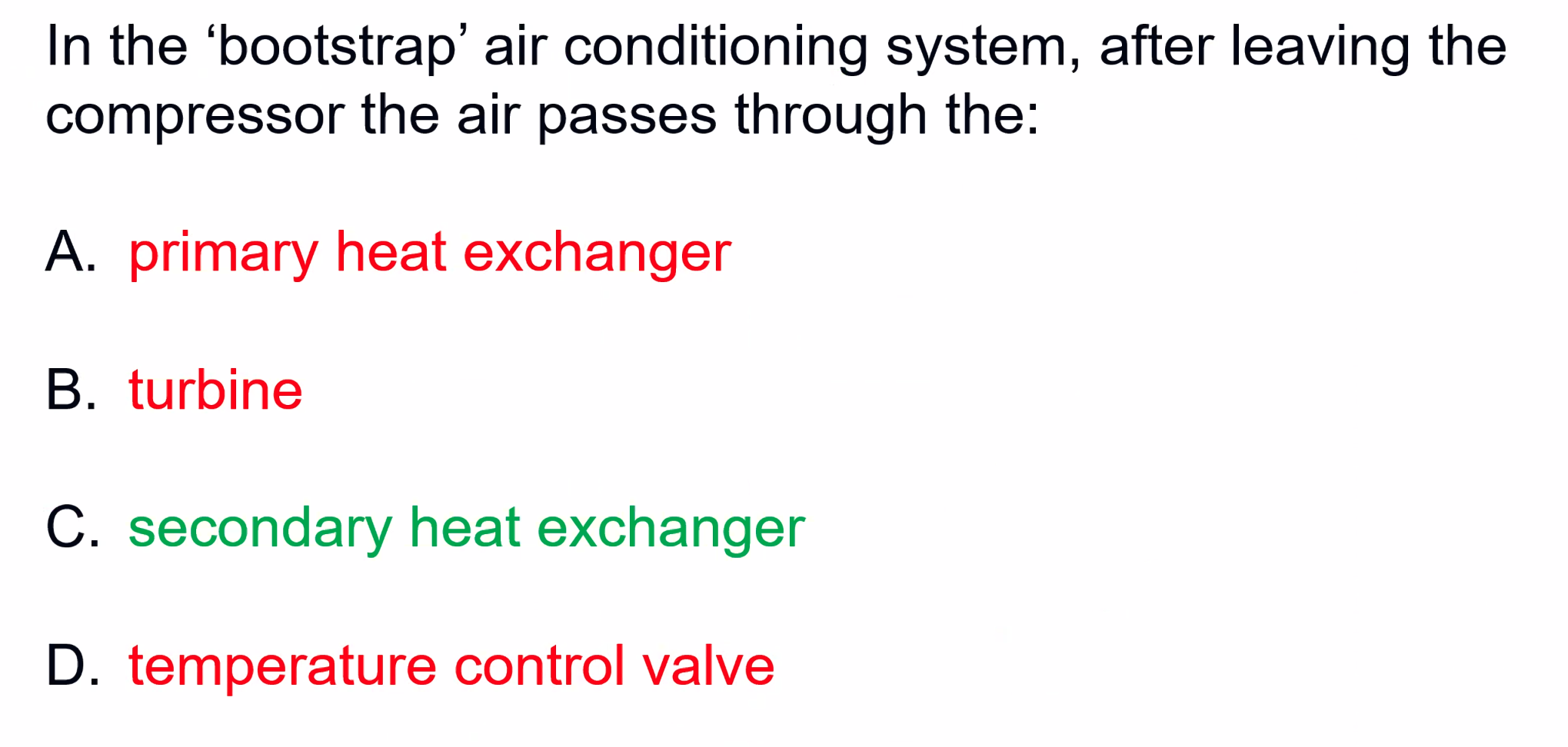
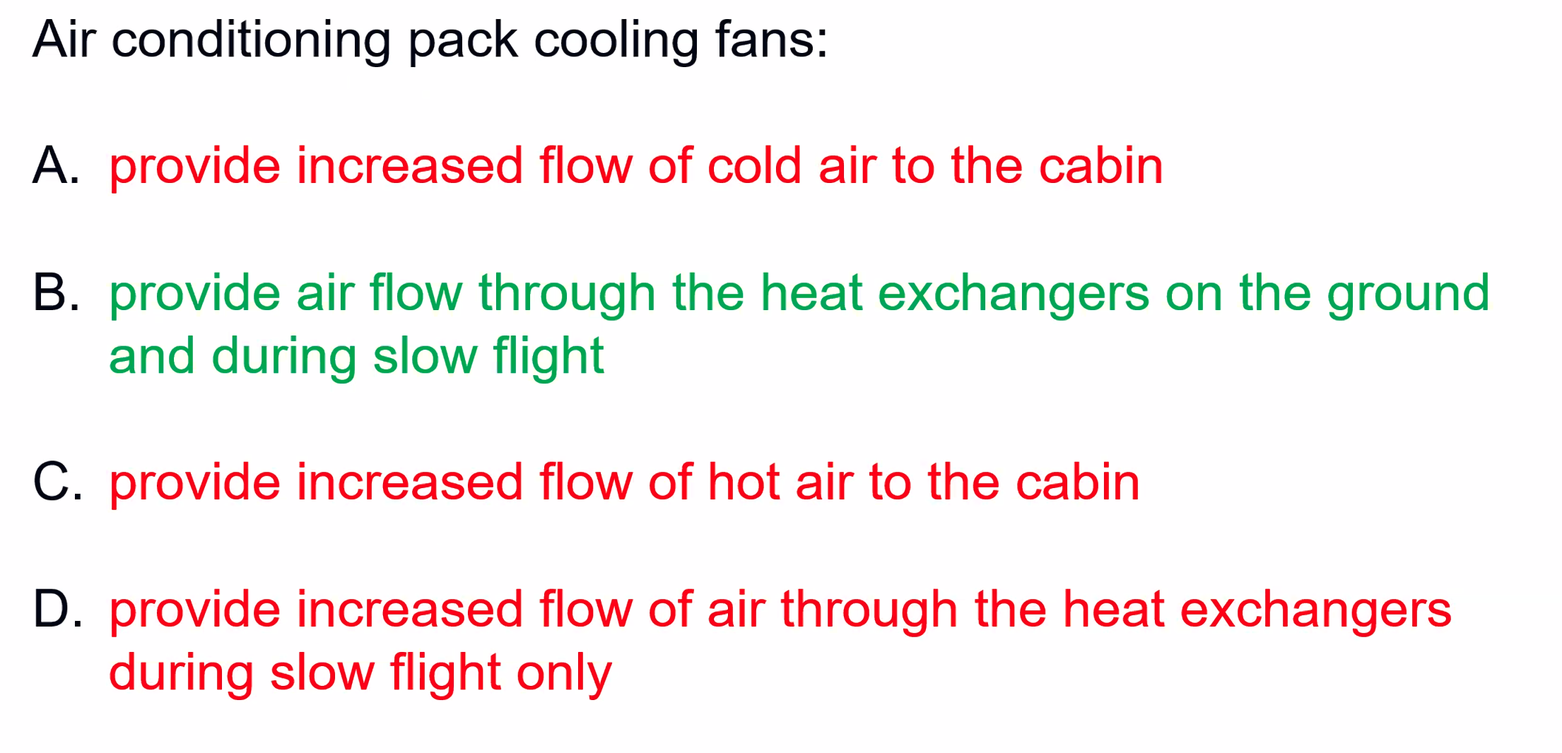
Mainly in use is the bootstrap system. The turbine moves the compressor and then we tap air from the compressor through a heat exchanger.
It cools it so much there’s an ice screen to prevent ice from getting through. Before the final NRV in the bottom right it is mixed with warm air again to
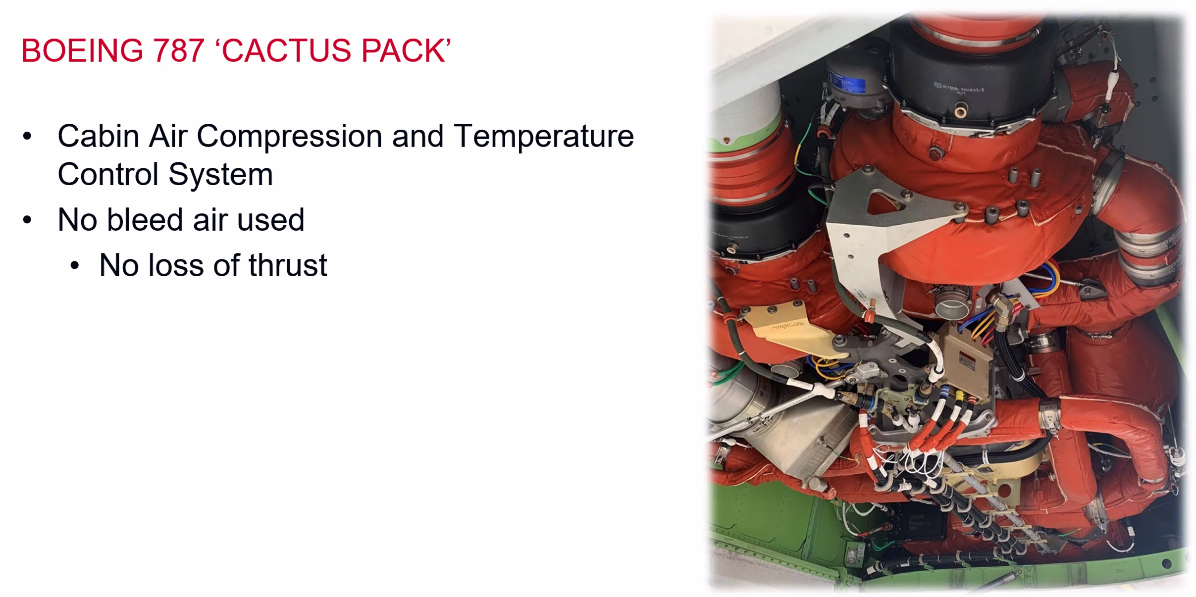
Uses electrically driven compressors, Boeing claim it reduces fuel burn by 3%. Also claim lower maintenance, cost and weight.
Fuel Systems
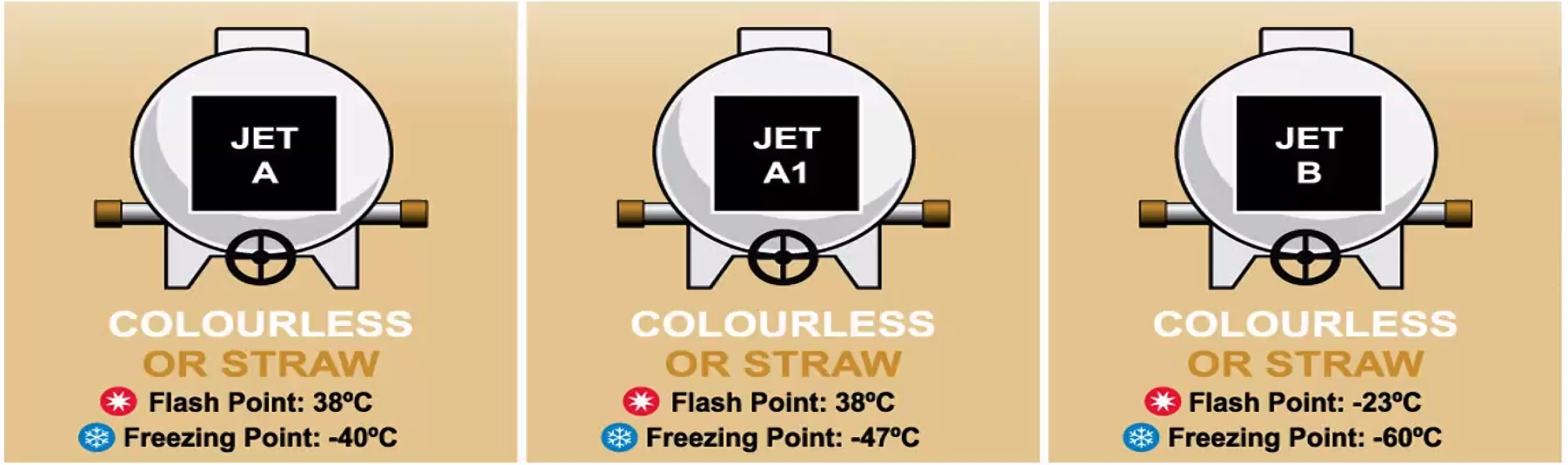
- Fuel types and Grades
- Characteristics
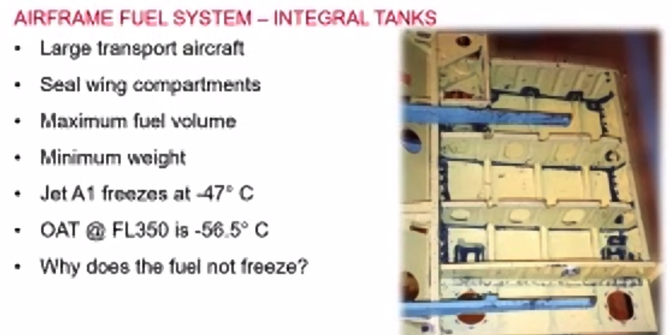
- Airframe Fuel system
- Storage
- Gauging
- Delivery
- Up to the HP fuel pump or carburettor
- Refuelling procedures
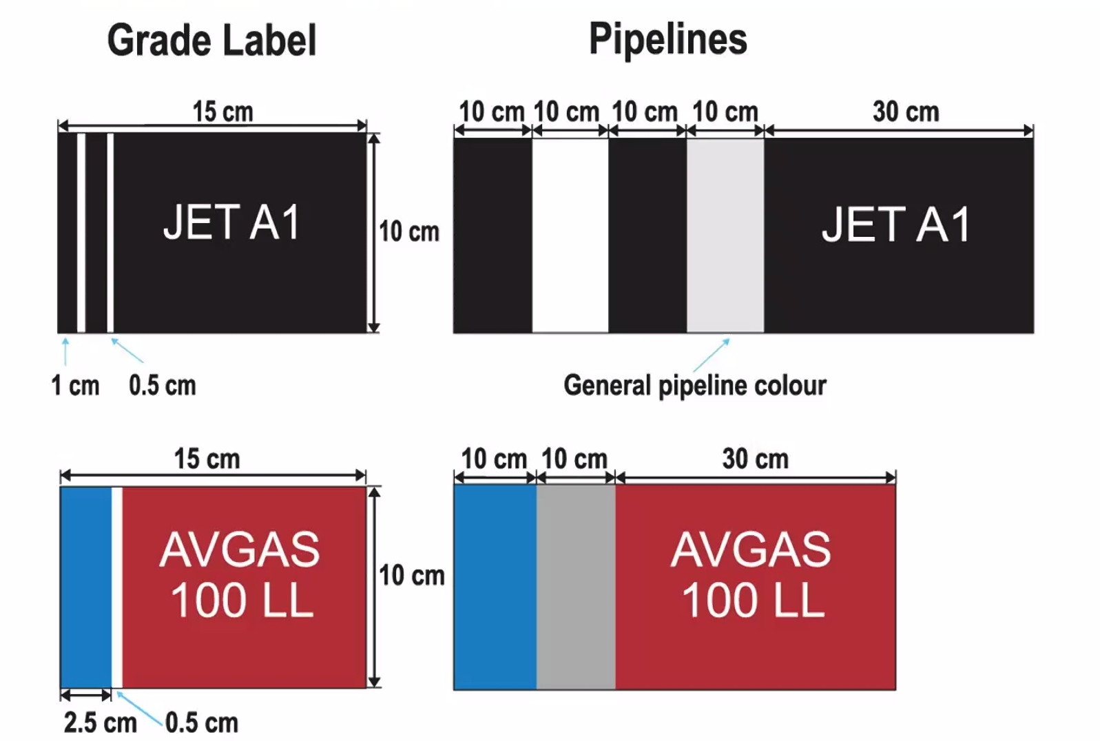
- Fuel quality control
The higher the number the higher the anti-knock resistance.
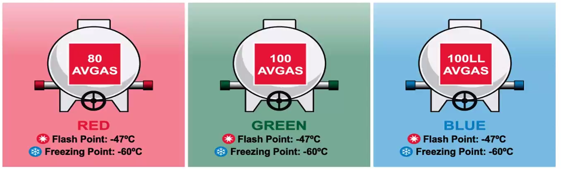
100LL - Low Lead.
If you have an aircraft that requires AVGAS80, you can use both 100 and 100LL. But not the other way around.
Friction & Heat Exchangers
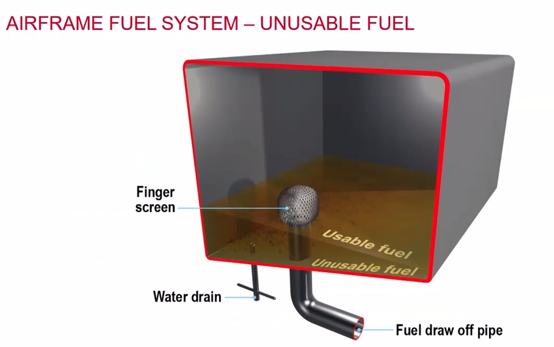
oil is lighter than water. Think about the oil spills where the oil is on top of the water.
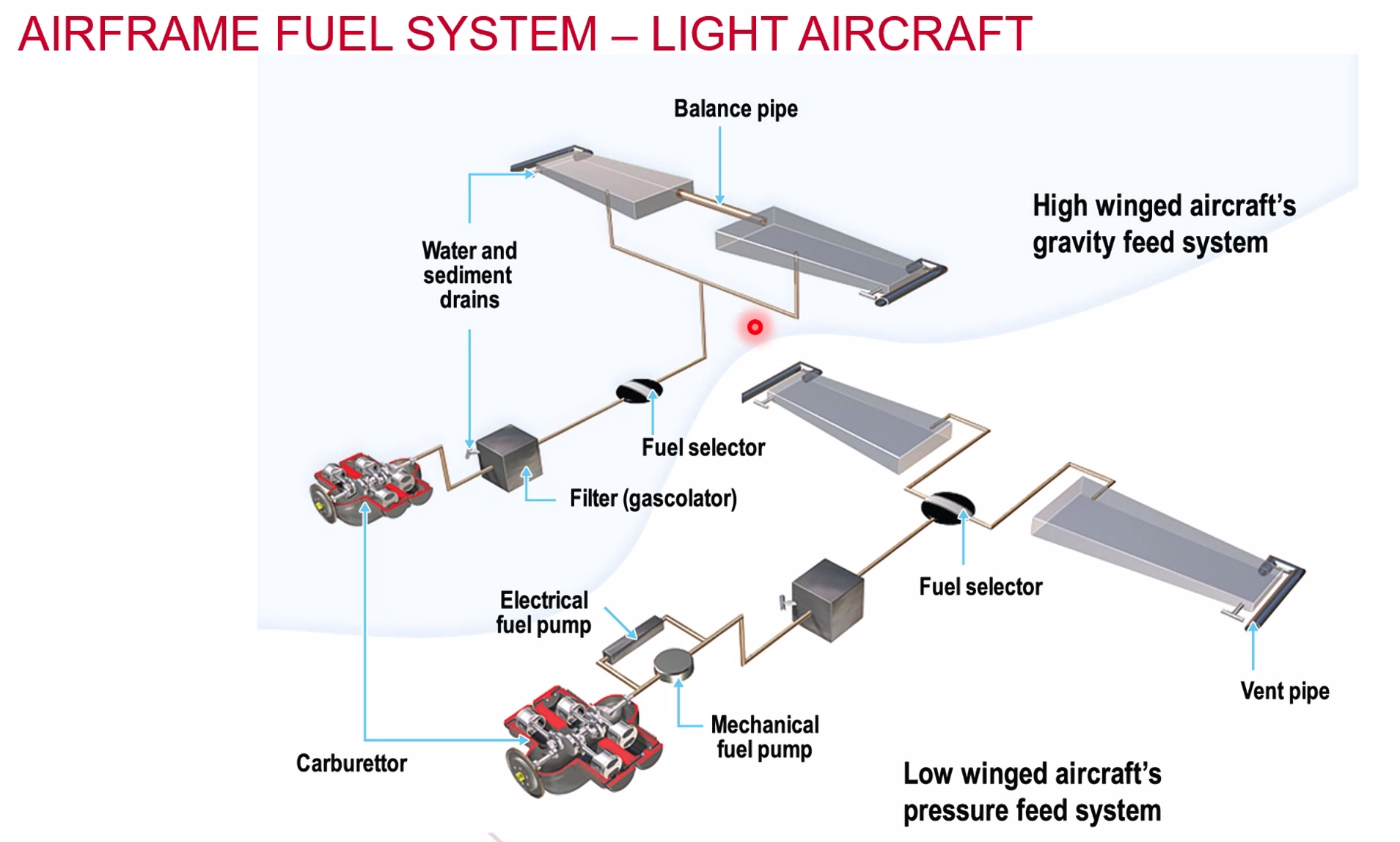
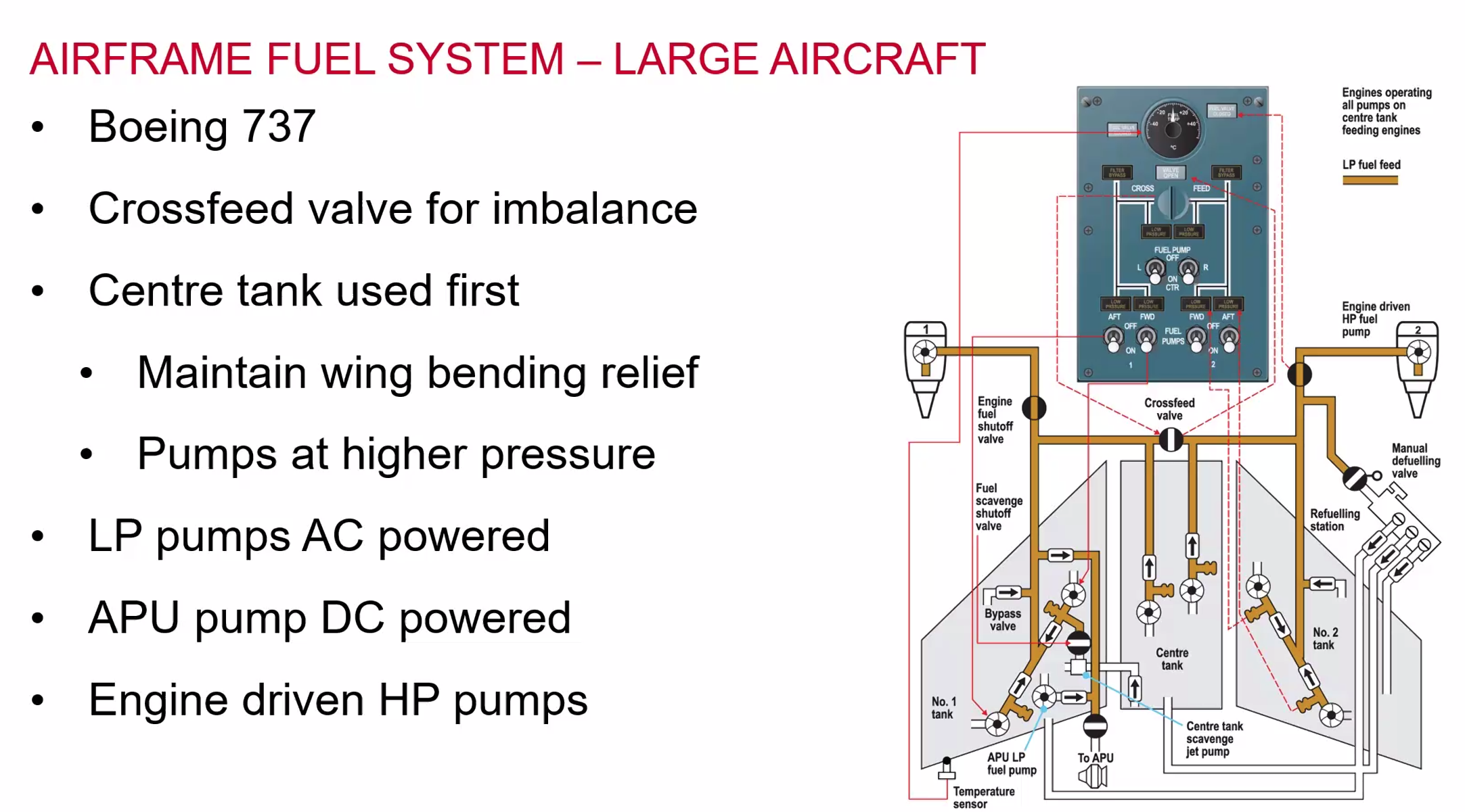
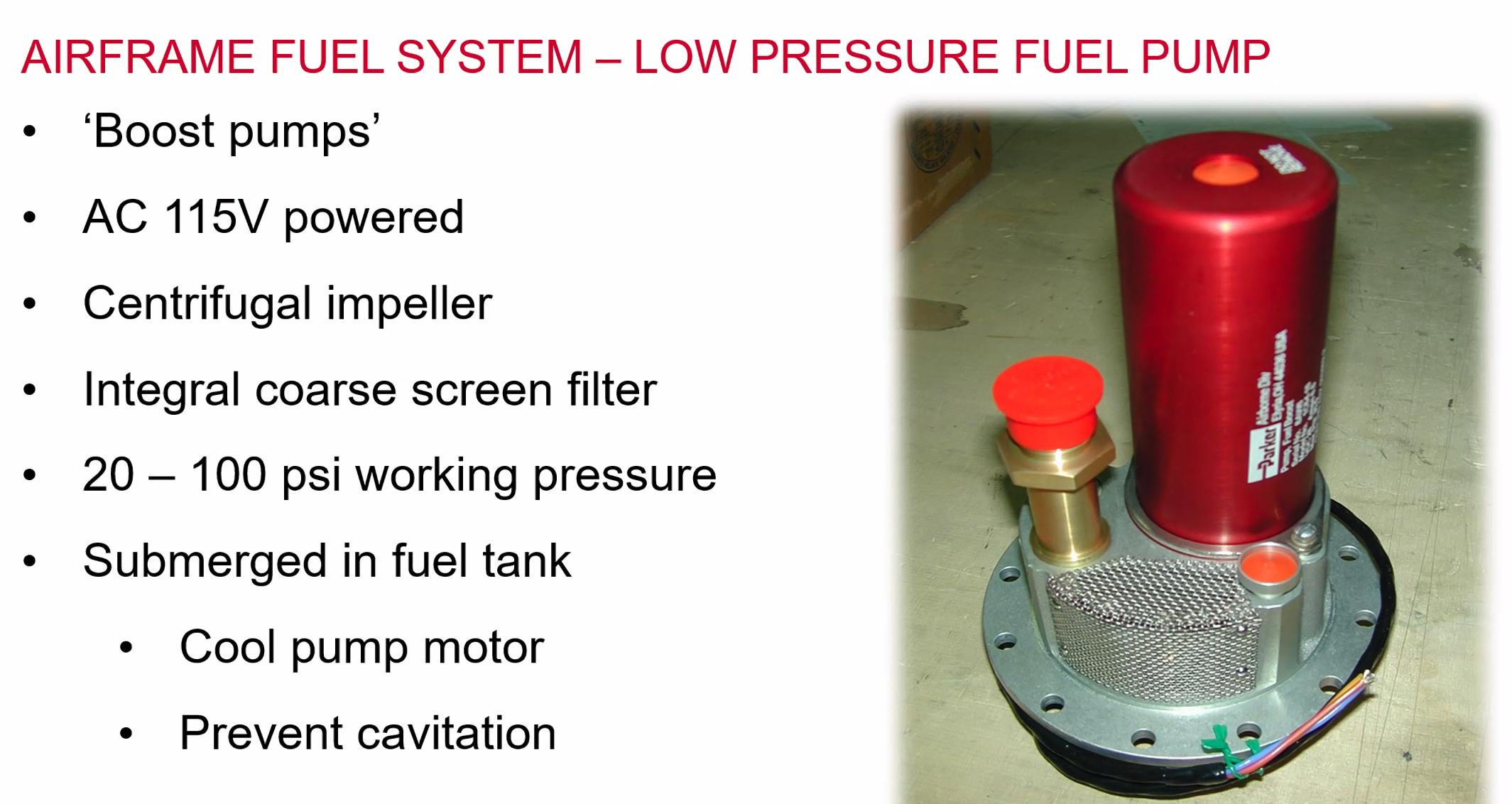
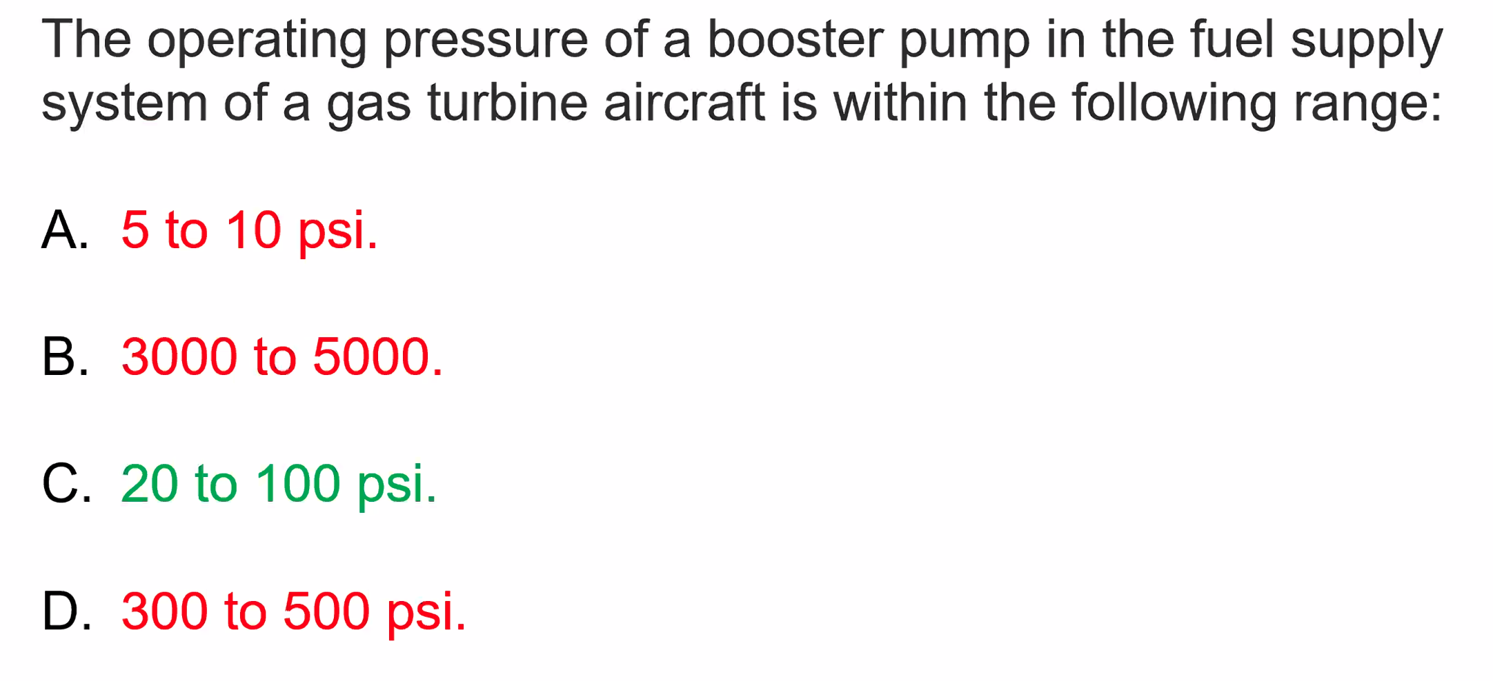
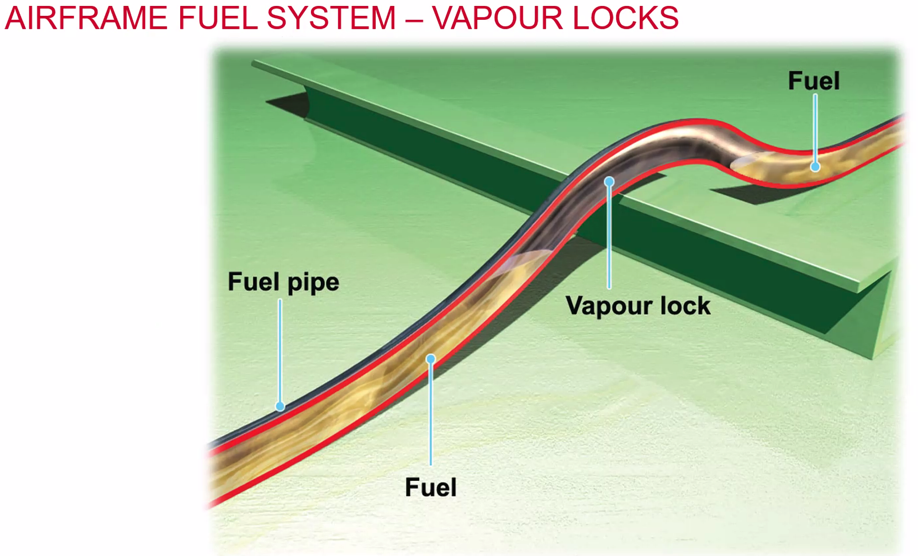
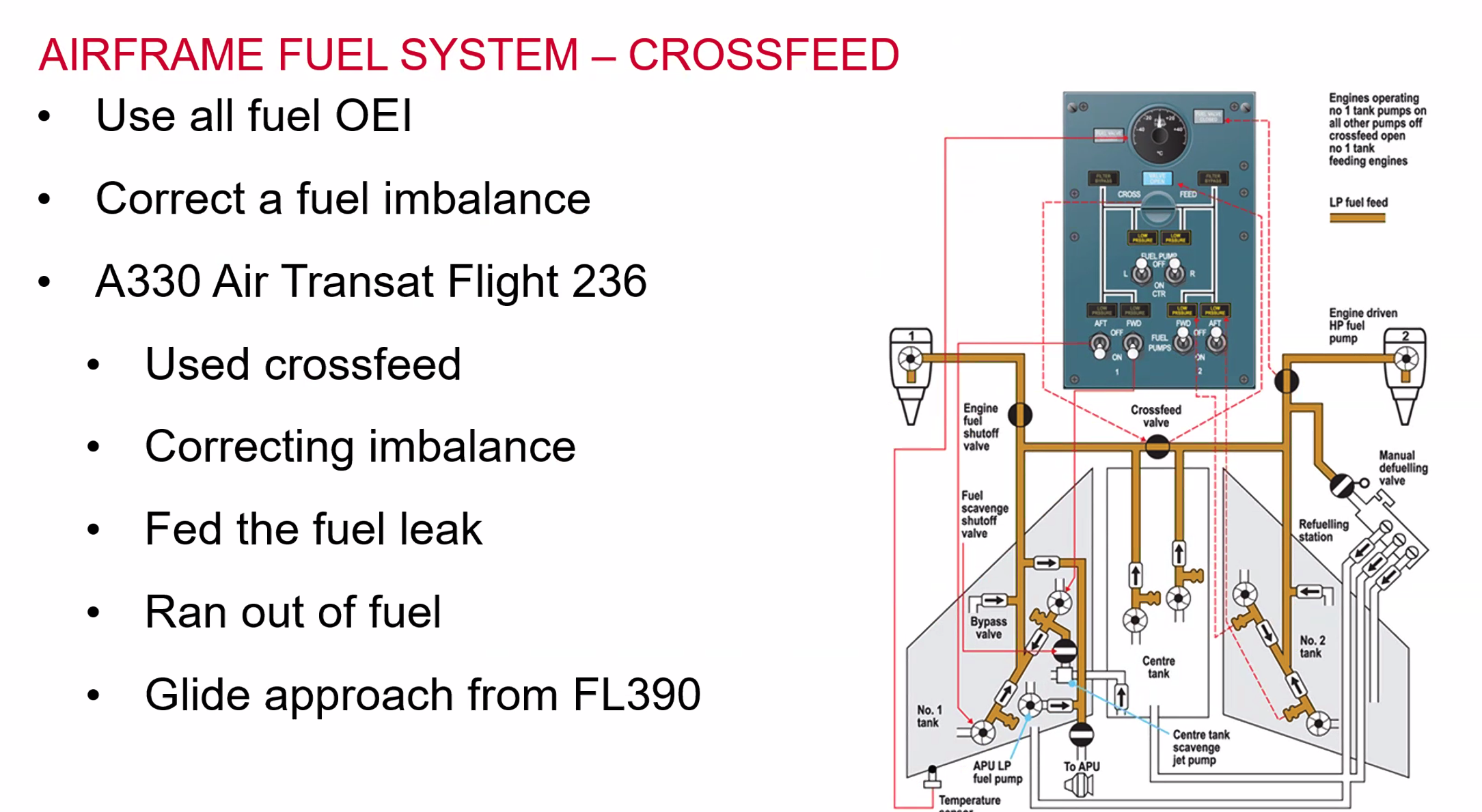
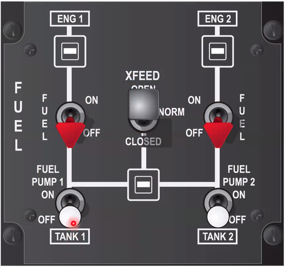
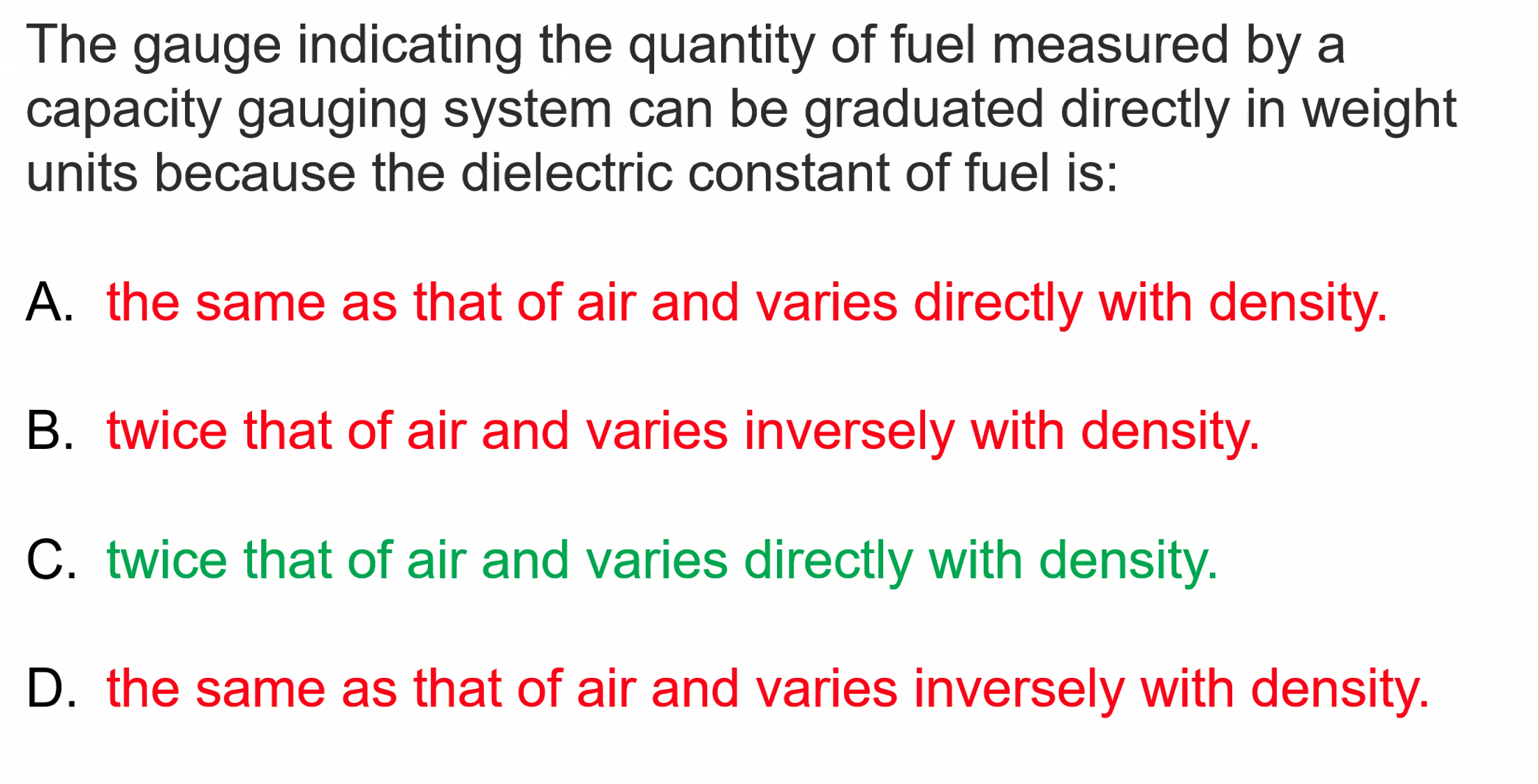
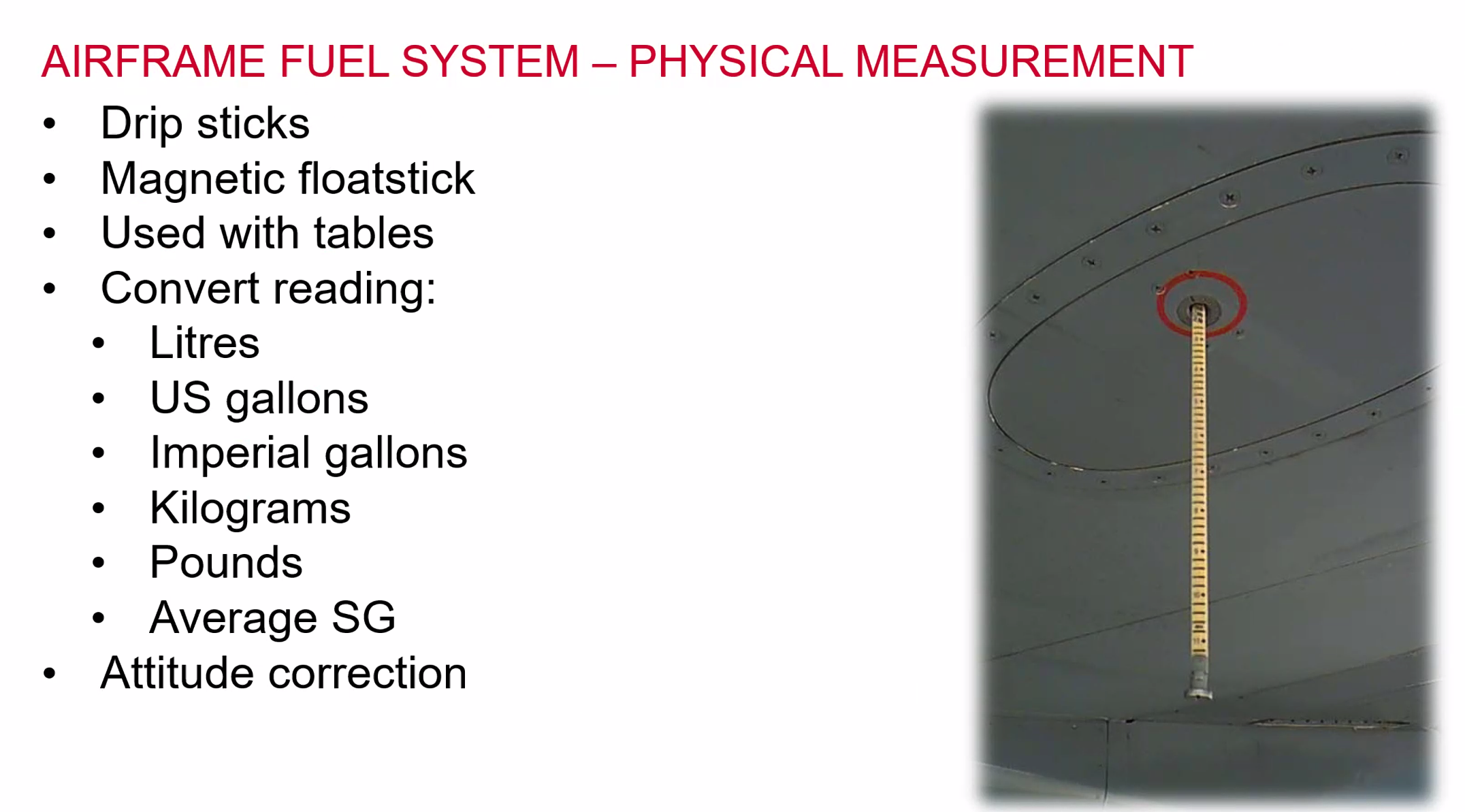
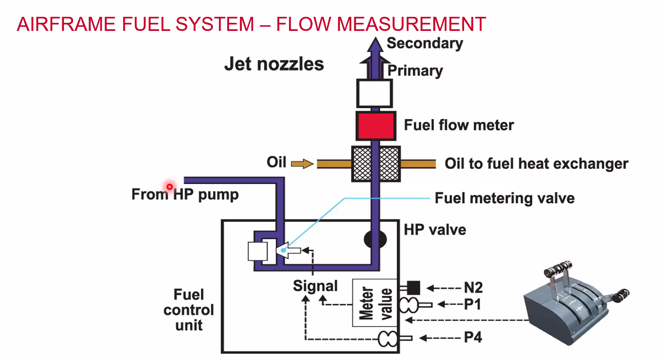
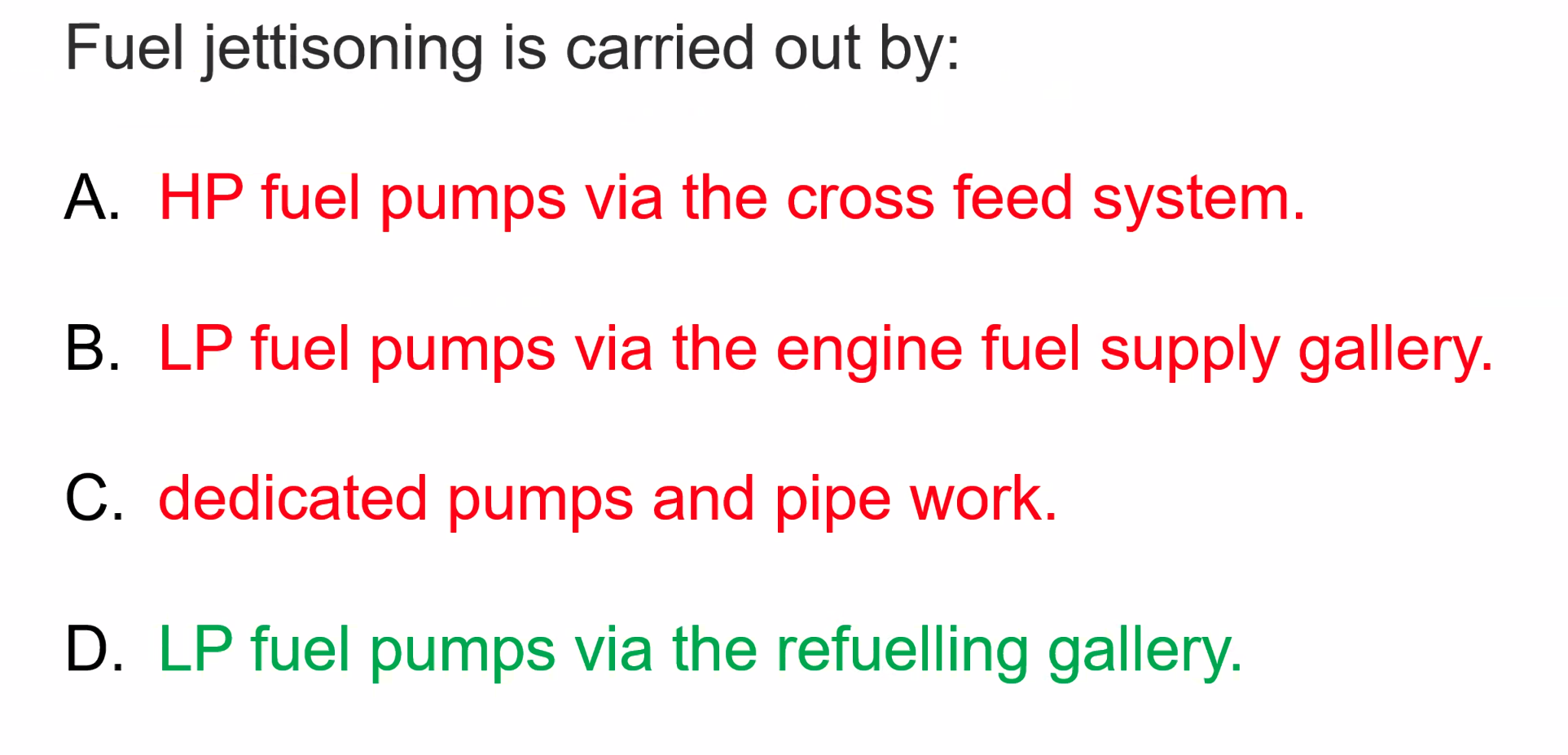
Fuel Jettison
Limited, Must leave sufficient fuel to:
- Take off
- Climb to 10000ft
- Cruise for 45 mins
Except in emergency, jettison is not permitted:
- Below altitude that allows evaporation of fuel
- In precipitation
- Over built-up areas
Jettison isn’t fitted to all aircraft - B737/A320 don’t require it because the Max Landing Weight allows for landing with a full tank. The actual ruling is if an aircraft can land after taking off and flying for 15 minutes then it does not require a jettison system.
With long haul aircraft there is a much larger gap between max take off mass and max landing mass.
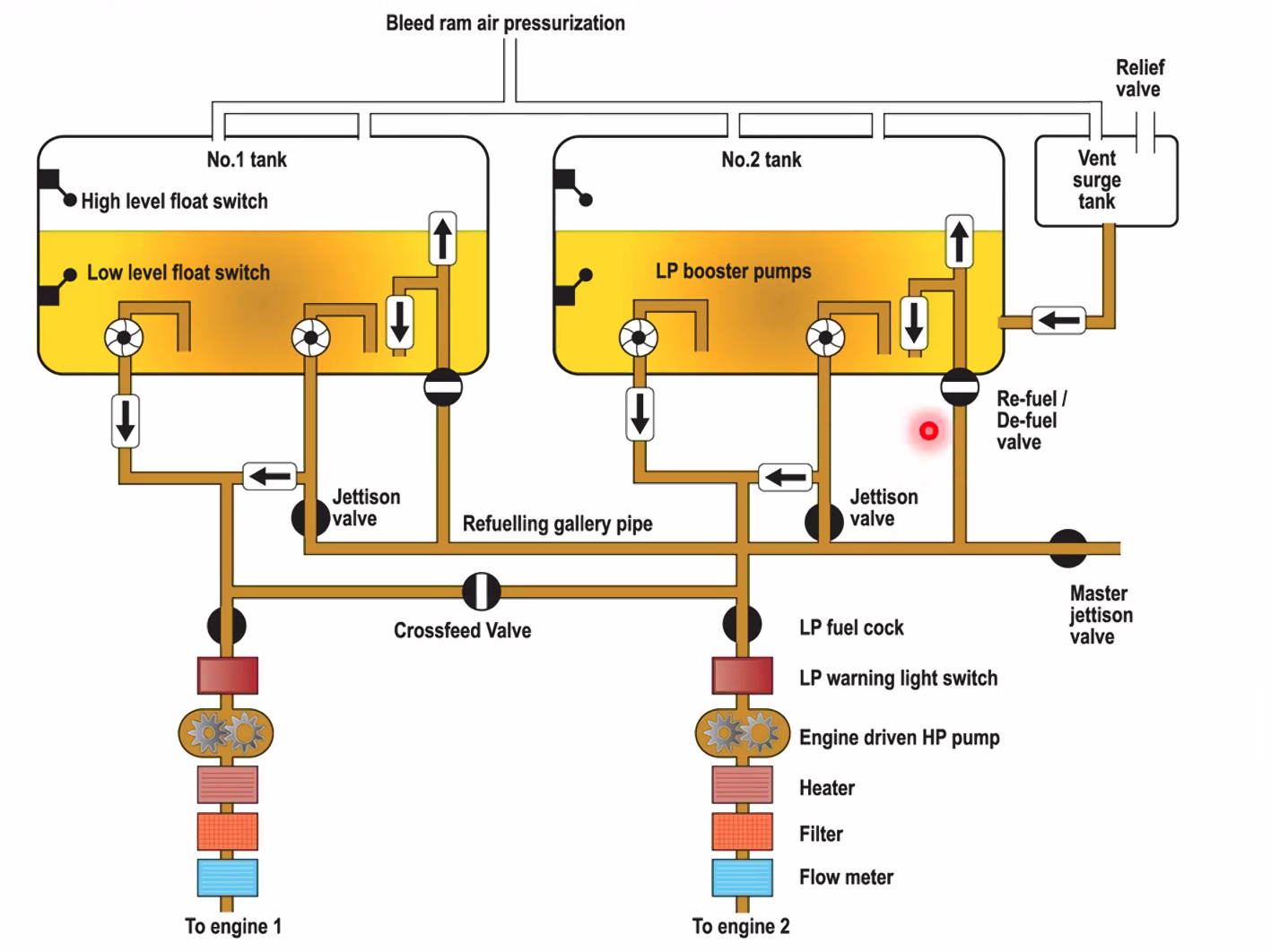
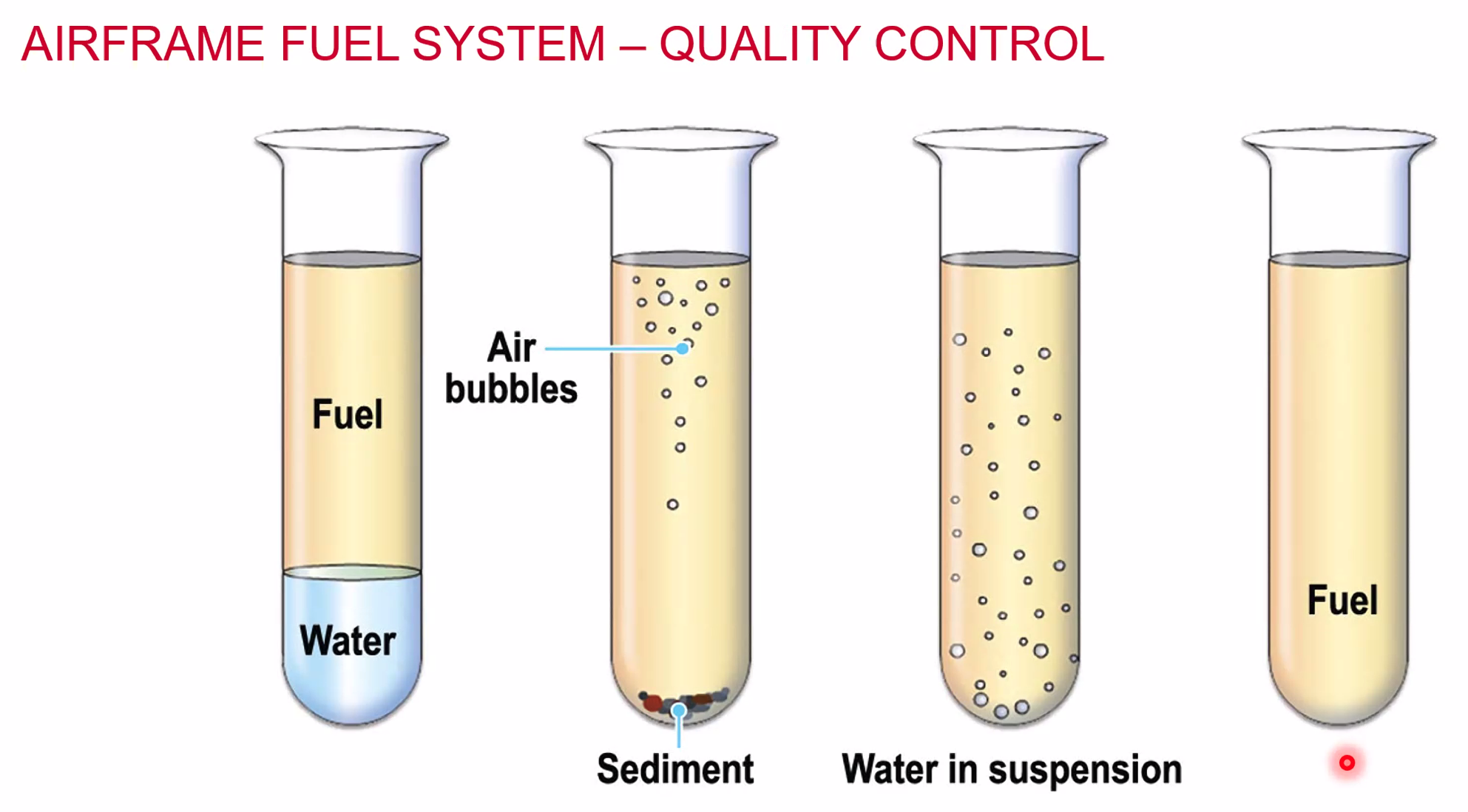
Refuelling starts when the filler cap is removed and stops once the caps have been refitted
- Bonding must always be done
- Fuel bowser to earth
- Aircraft to earth
- Fuel nozzle to aircraft - to get the same potential difference and reduces the chance of static sparking.
Electrics
- Basic Electrical Theory
- Direct Current
- Alternating Current
Simple Electrical Circuit
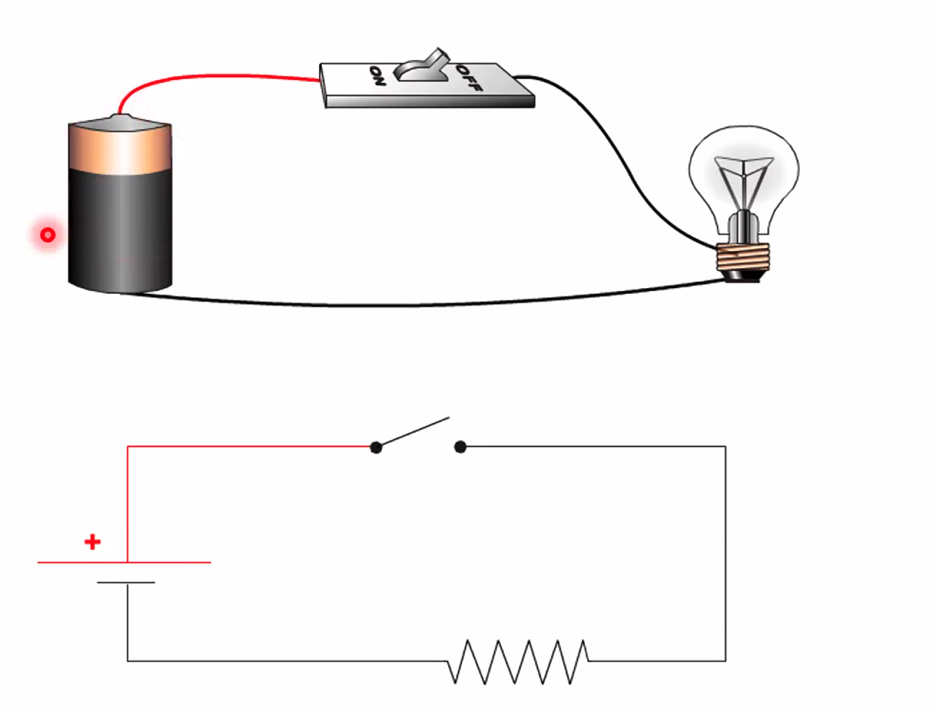
Single cell battery, representing by a long and a short line on a diagram. Followed by a switch. Followed by a resistance load (in this case a light bulb).
In the single cell battery
- there is an anode and a cathode
- There is a force within the battery, or an Electromagnetic force with a potential difference
For a resistance there is a load that is required which will be resisted against.
Definitions
- Volts - potential difference or the electromotive force
- Symbol: U or V for the value. For example U = 28V but we would never say V = 28U
- Amps - flow of electrons / current. Imagine a water trough with a dam at one end you need the flow to use the power.
- Symbol: I or A, I is for the intensity of the current and again we would say I = 6A
- Ohms - resistance to the flow
- Symbol R or Omega, example R = 8Ohms
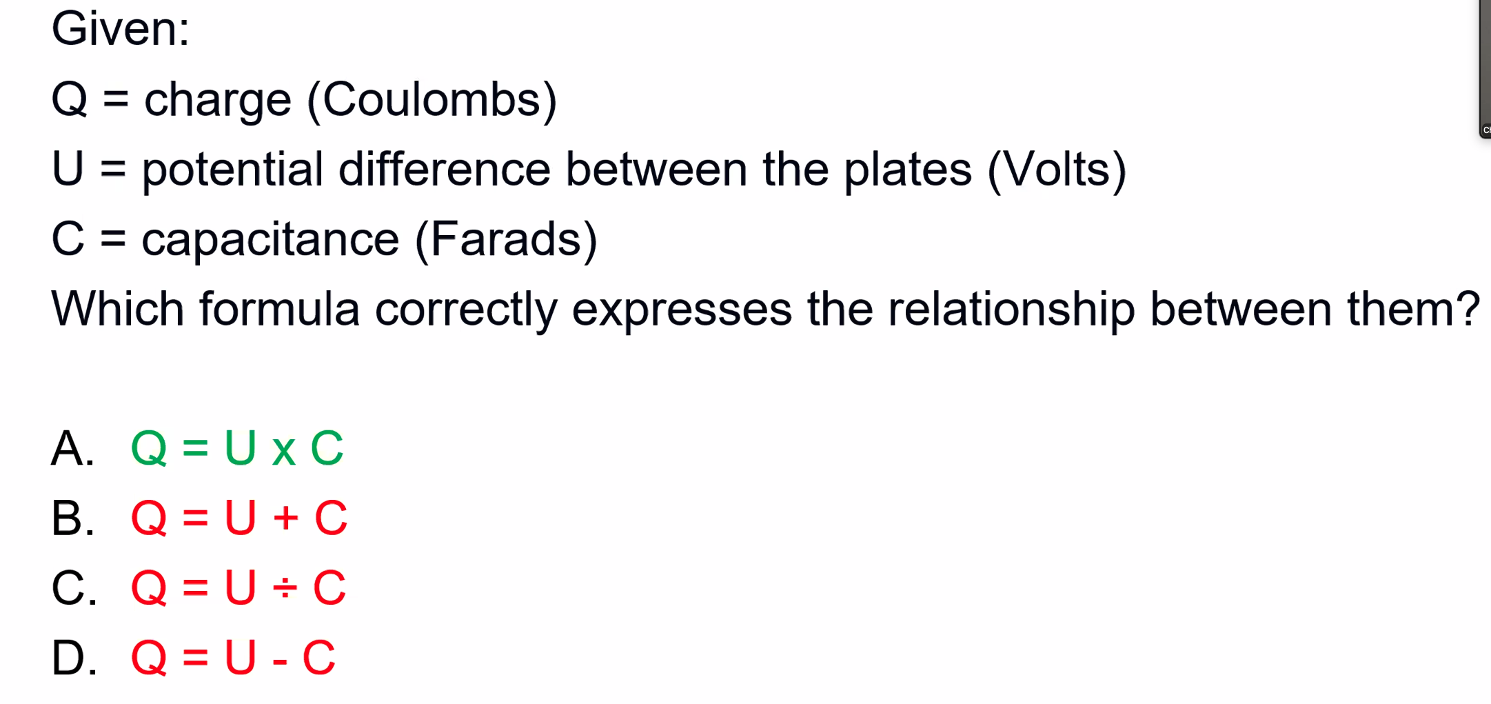
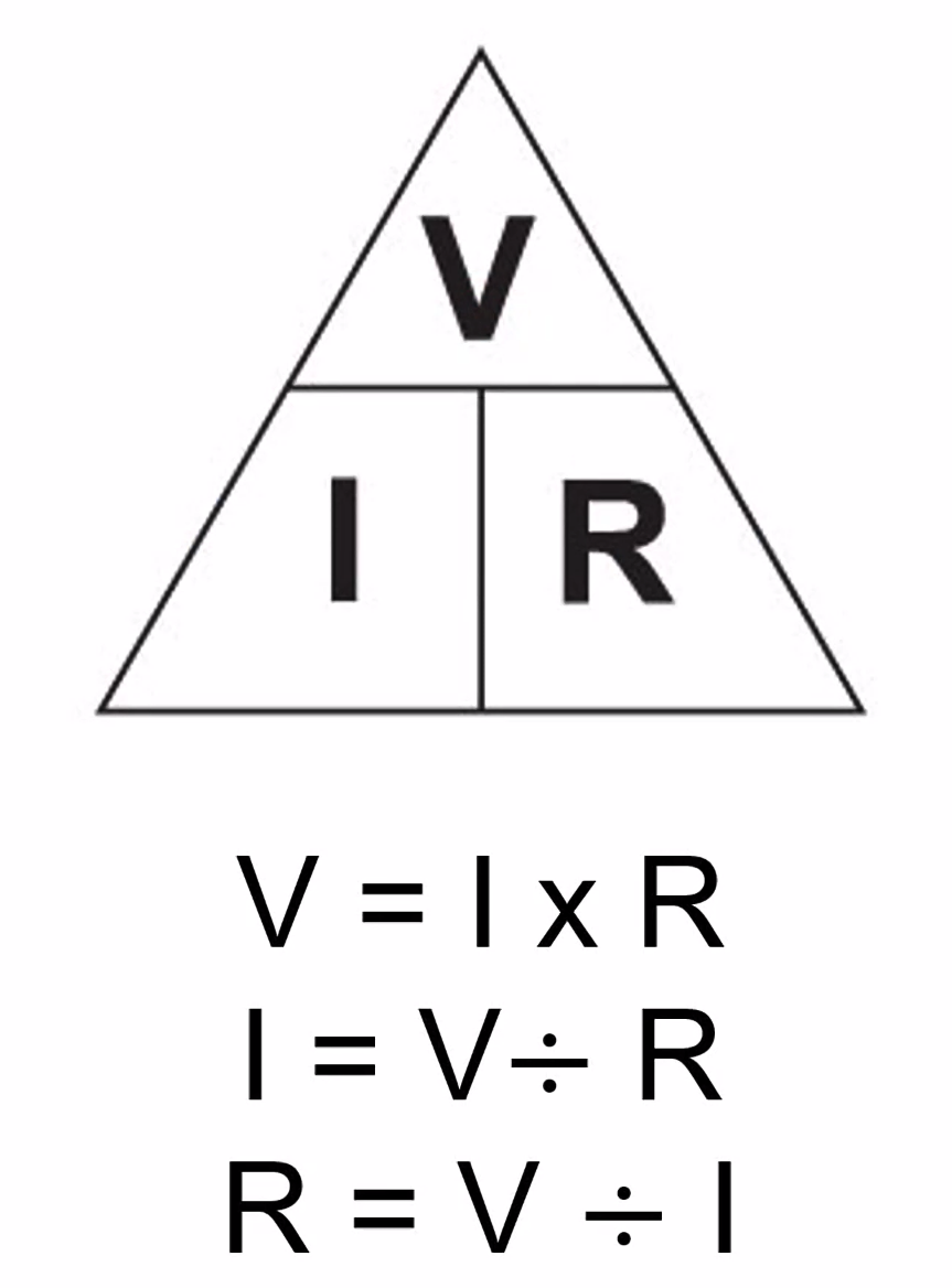
We won’t be asked to calculate the value anymore.
Short Circuit
- where no current drawn for ‘work’ (light, heat, motive power)
- It has to go somewhere so the whole circuit will heat up - fire risk!
- Over-current causes the same effects but it may be transient
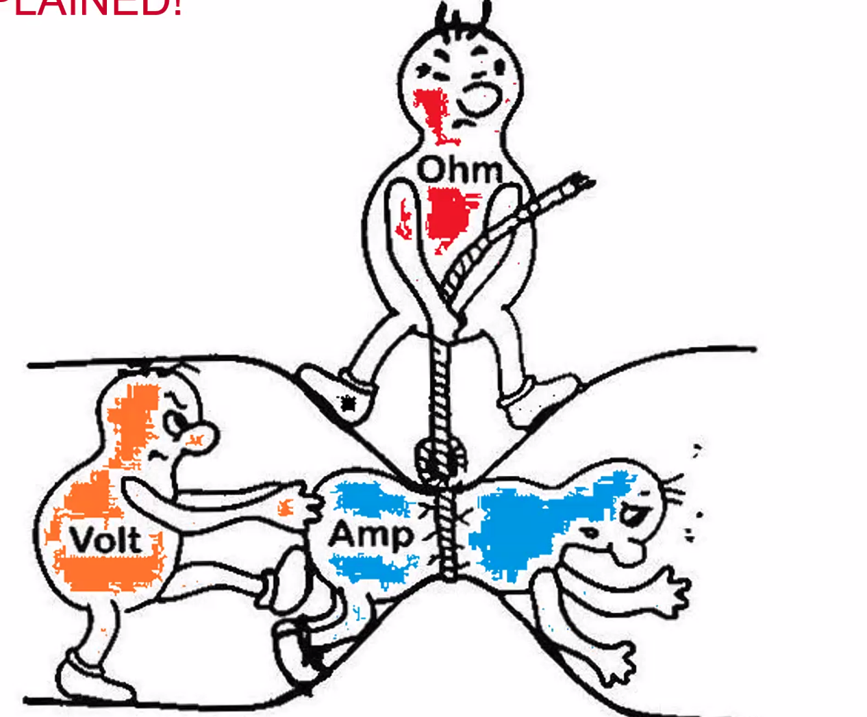
Electromotive force is measured in Volts and current is measured in Amps
Current Flow Effects
When current flows through a conductor, it generates:
- Heat
- Light (infra-red)
- Magnetism (corkscrew field in direction of DC travel)
Resistance of a conductor/cable
Diameter
- A fat cable - low resistance
- thin cable - higher resistance
Length
- a long cable - higher resistance
- short cable - low resistance
Material
- Positive temperature co-efficient
- Negative temperature co-efficent (R 1/T)
Positive temperature co-efficient Think of a thin wire. If the temperature increases, the resistance increases and the I (current) decreases
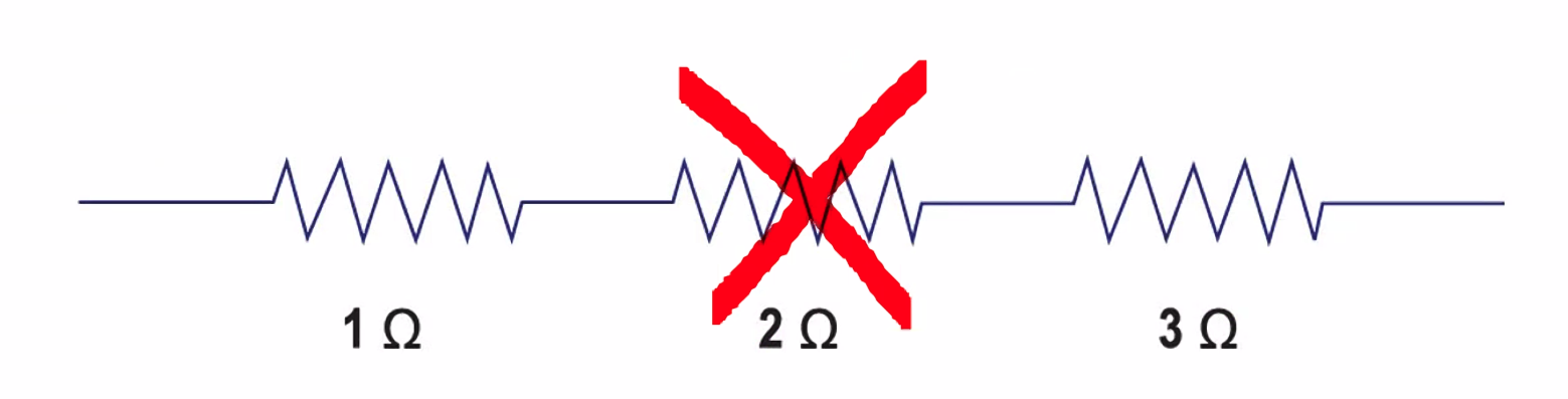
3 Resistors connected in series
- total resistance? add all.
- So in the image below total resistance is 6 ohms
- One of the disadvantage of series is one wire results in a single failure so no current can flow - think cheap party lights.
SAR - Series? Add Resistance. PSA - Parallel? Sum Amps
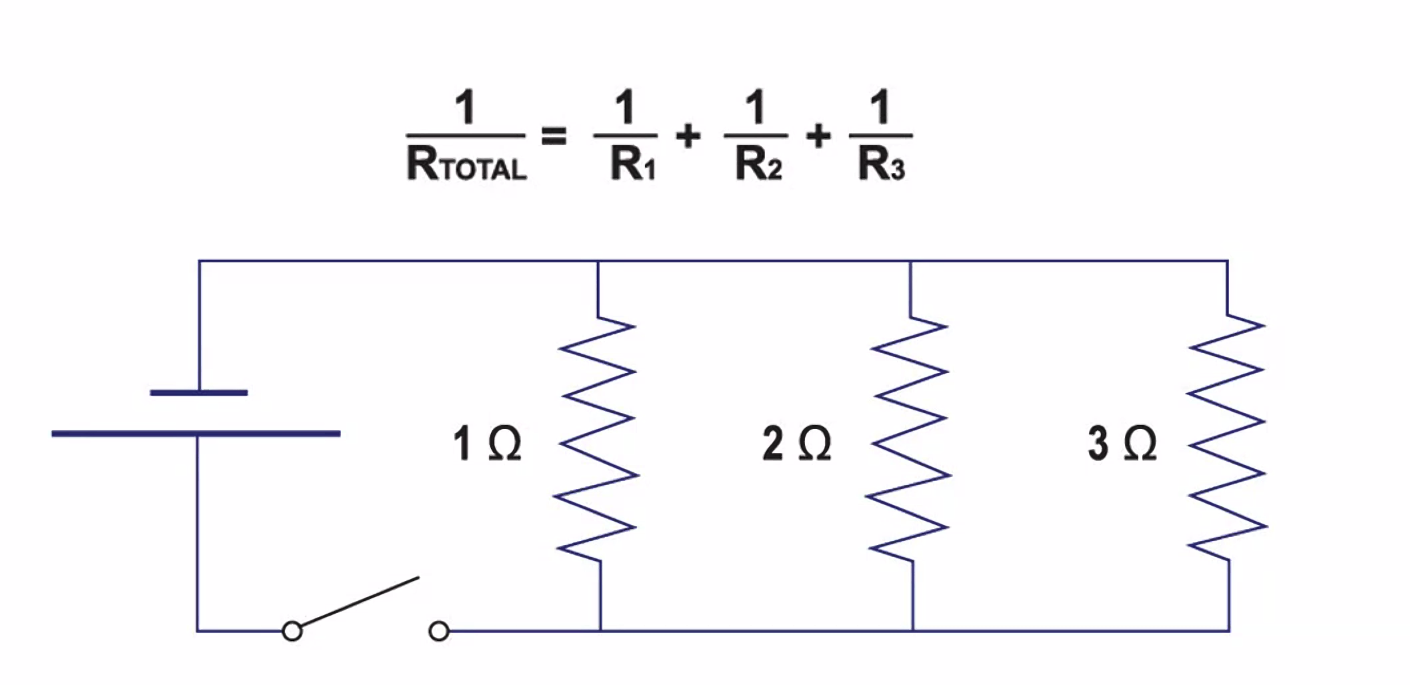
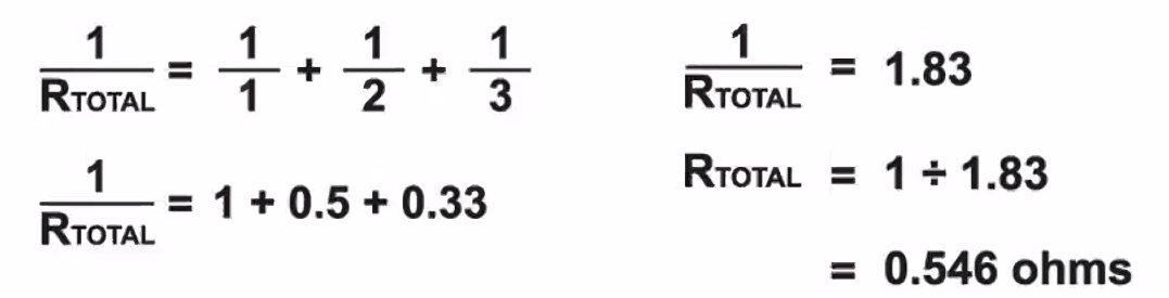
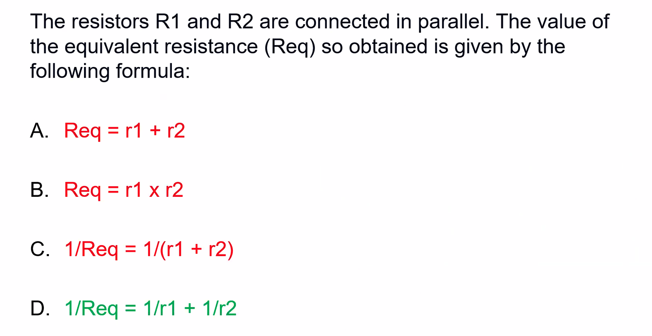
3 Resistors connected in parallel
- Total resistance, inverse relationship so total is sum of inverses and is ALWAYS less than lowest.
- One fails - remainder works.
- However, if there is lower resistance there MUST be higher current.
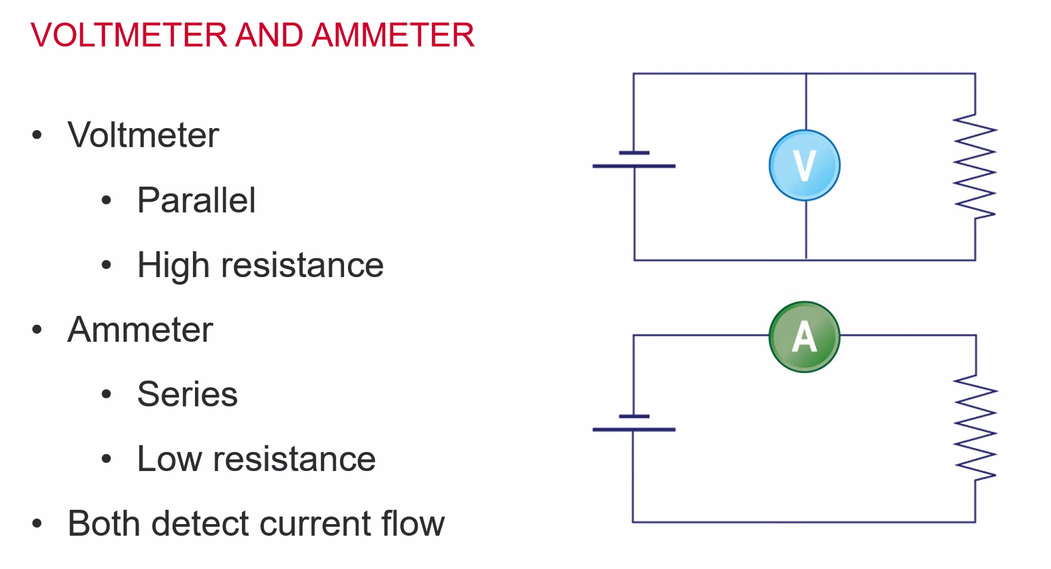
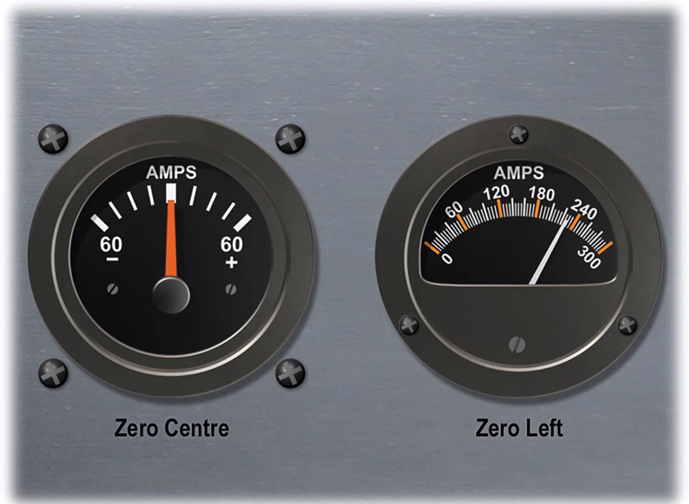
Two types of Ammeter
- Zero center, which shows discharge and charge.
- Zero left, shows total amps being drawn through the circuit
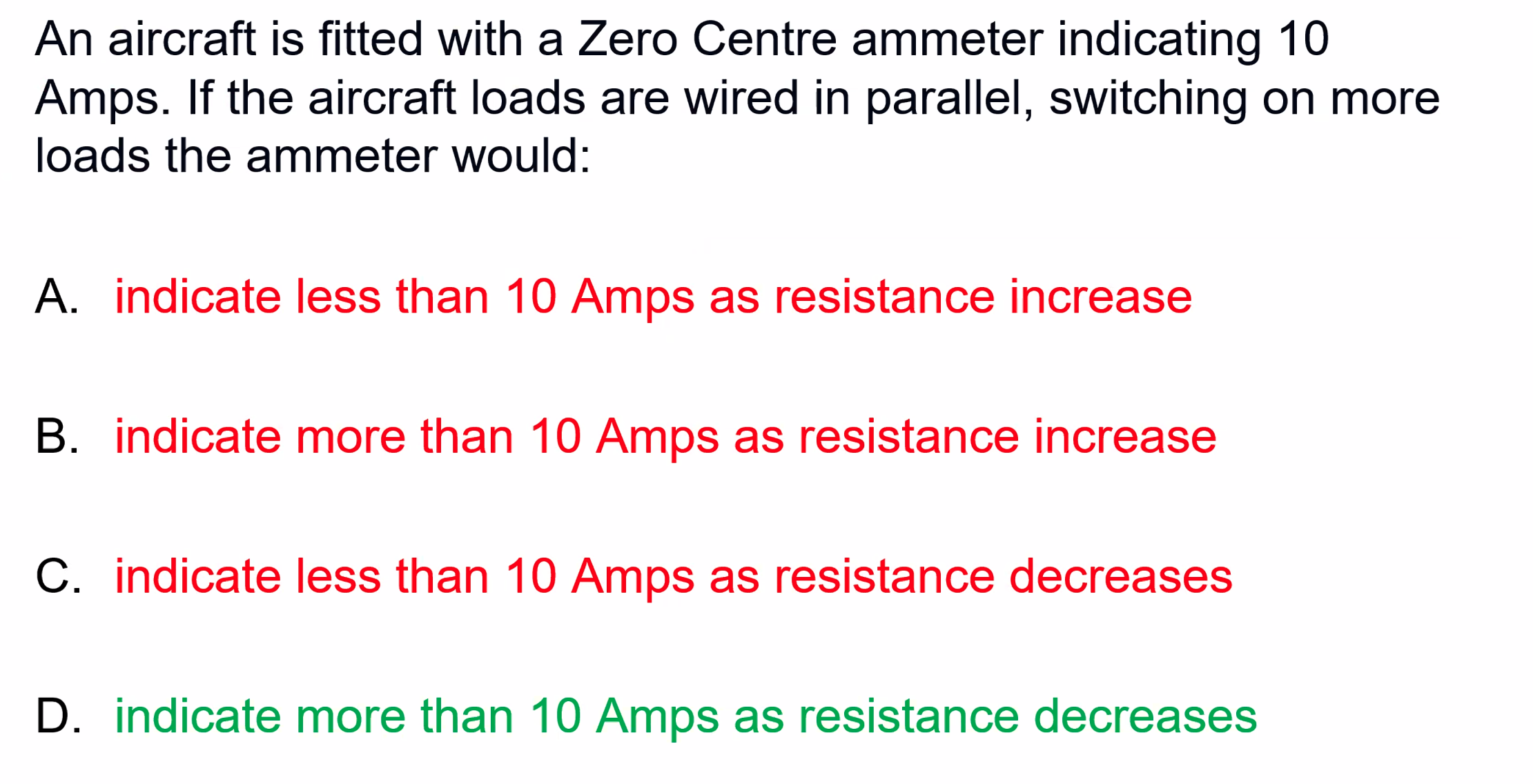
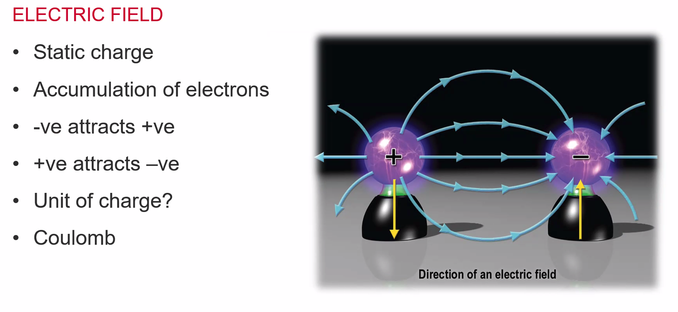 If we were to add a magnetic field - we would create electro-magnetism.
Direct Current Electrics
Batteries
- Batteries store energy as chemical energy and then can release as electrical energy
- Various types
- Aircraft battery is used for:
- Aircraft starting
- Emergencies
Battery Types:
- Lead Acid
- Nickel-cadmium
- Lithium-ion
- Lithium-polymer
All of these can go ‘thermal’ where a thermal runaway can lead to a fire.
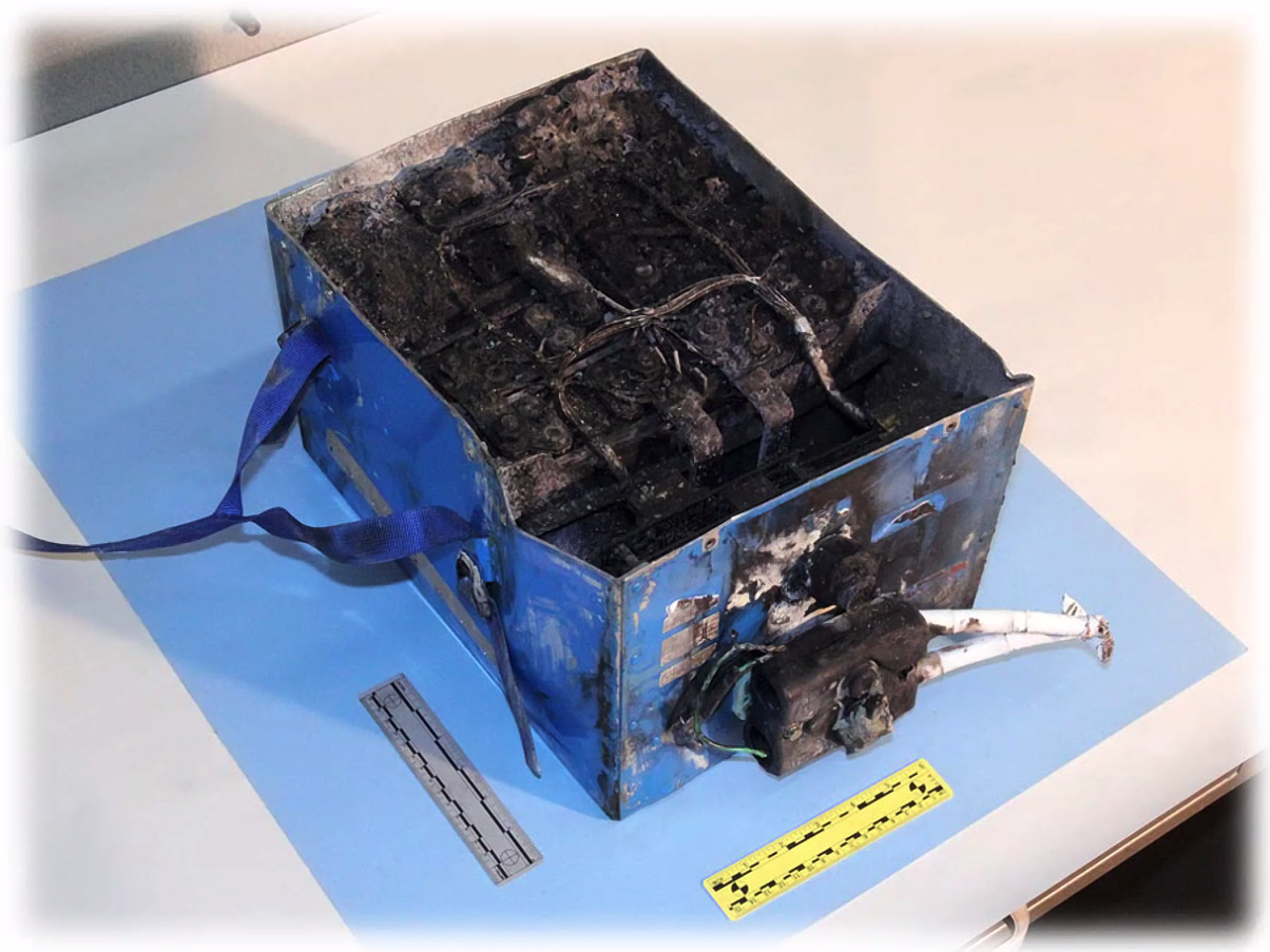
Batteries - second cell
- lead-acid
- nickel-cadmium
- lithium-ion
- lithium-polymer
- rechargeable
- 112% of voltage required to recharge
- rated in ampere/hours
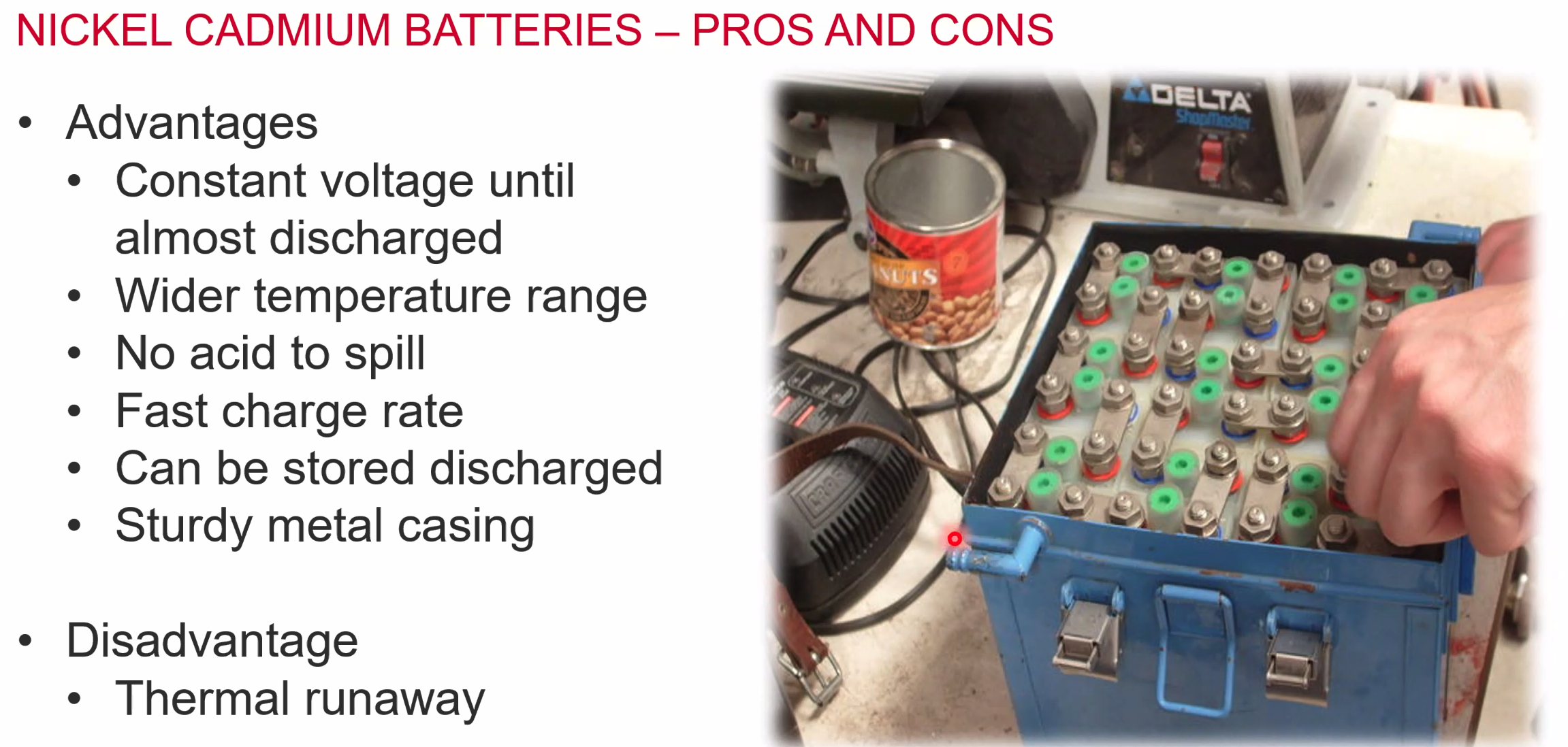
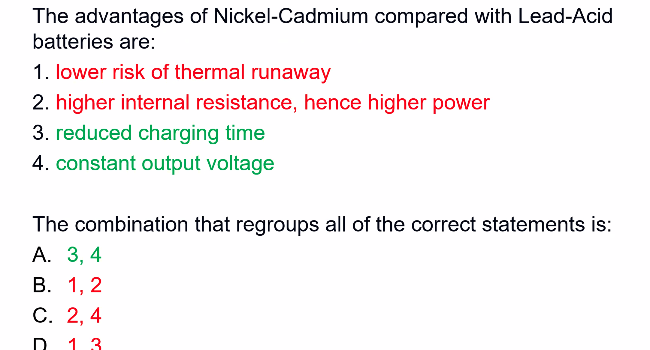
Nickel Cadmium battery
- most likey to be in an aircraft. Contain a Potassium hydroxide gel electrolyte
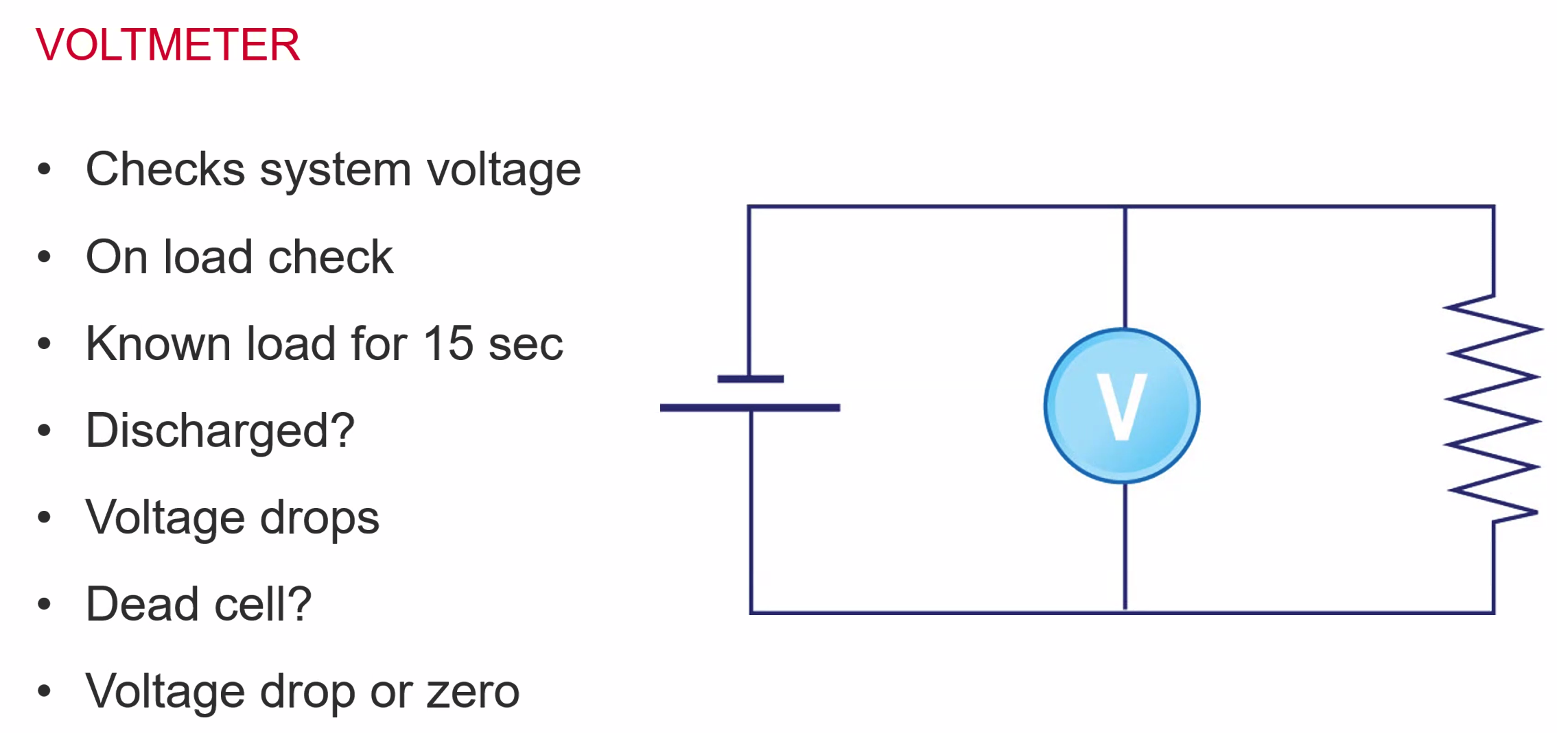
- 1.3V off load
- 1.2V on load
- Constant voltage on discharge
- Measurable discharge
Protects agains:
- Overheating
- Overcharging
- Internal Short Circuit
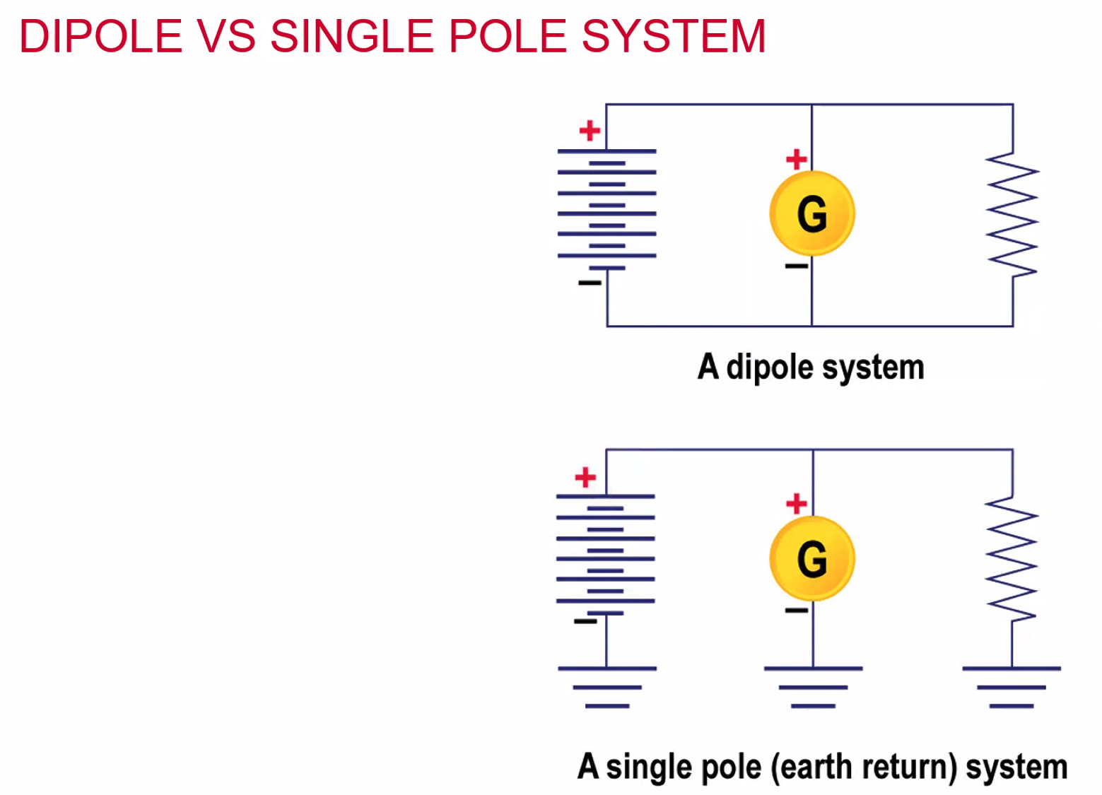
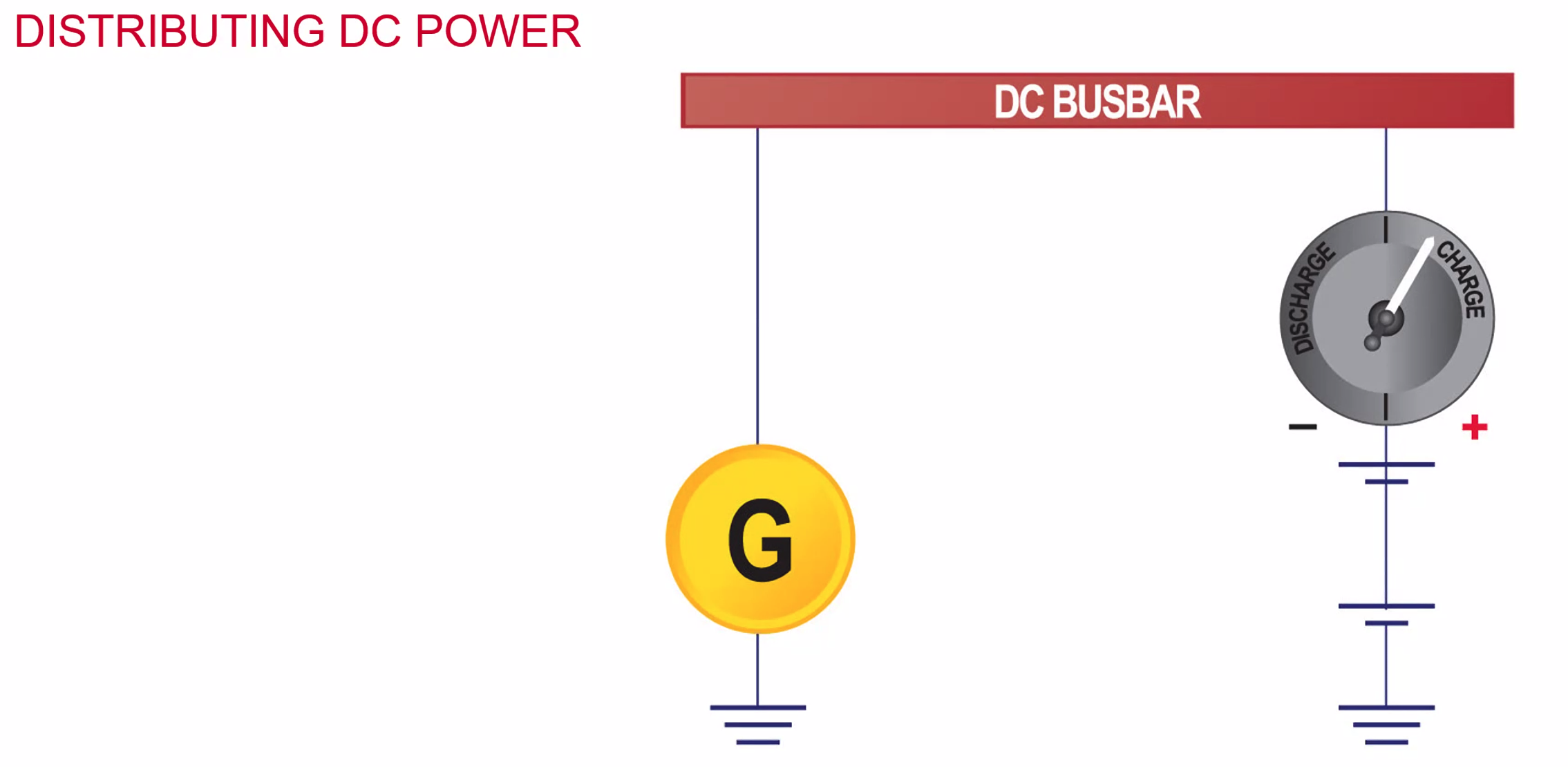
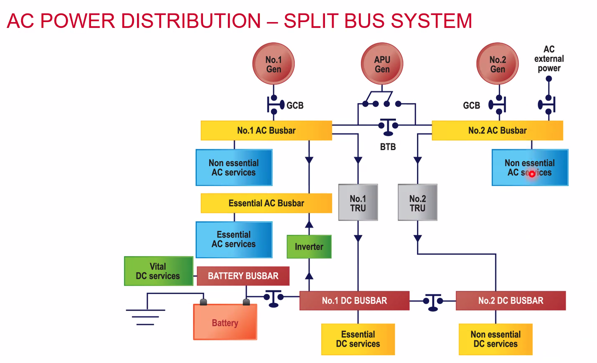
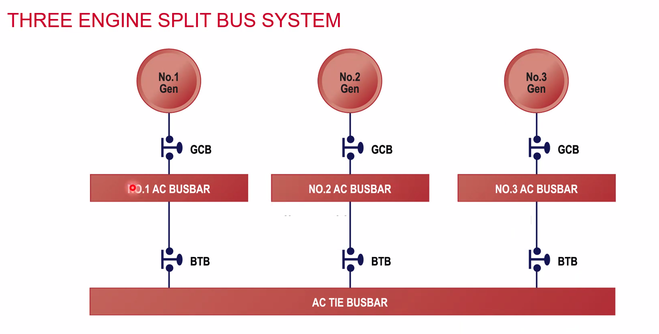
- Busbar - is essentially a lump of metal
- Battery power goes to the bus bar
- Generator goes to the bus bar
- Services take power from the busbar and connected in parallel
- There is multiple redundancy with this.
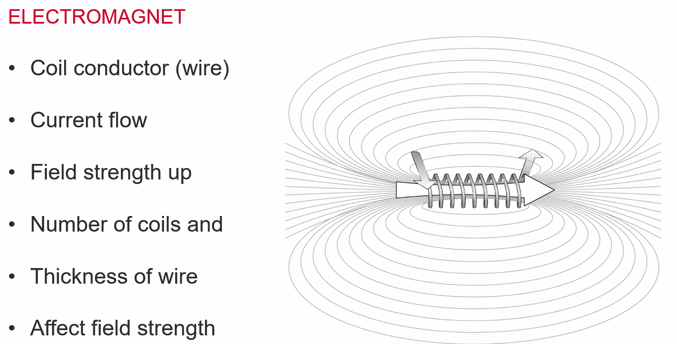
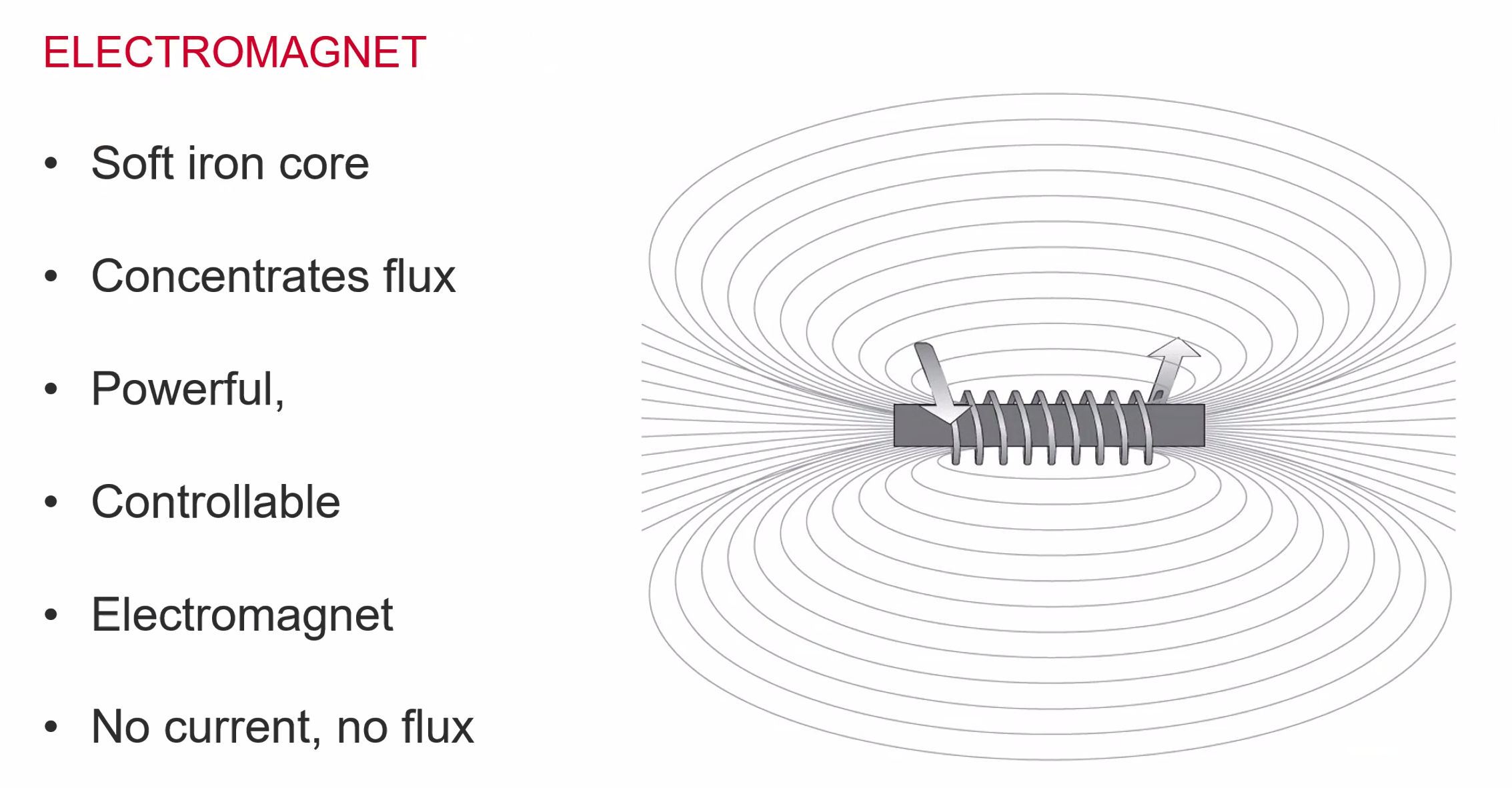
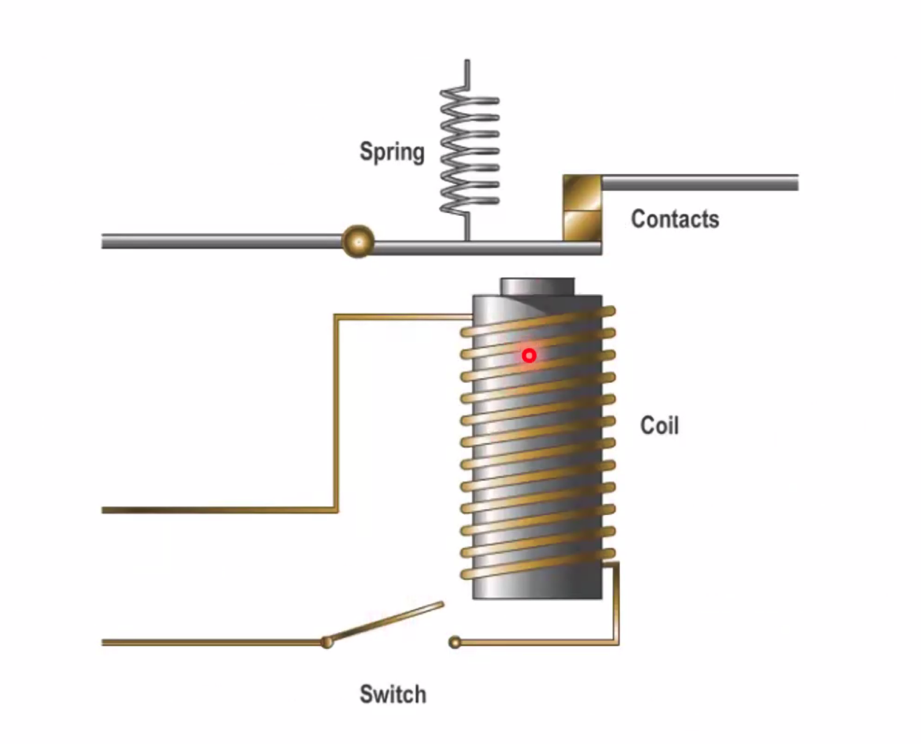
Using this information we can create something called a Solenoid - uses an electromagnet to move something, a valve a switch. Is the current on? it’s a magnet. Current off? magnet stops and the spring pushes it back to the original position.
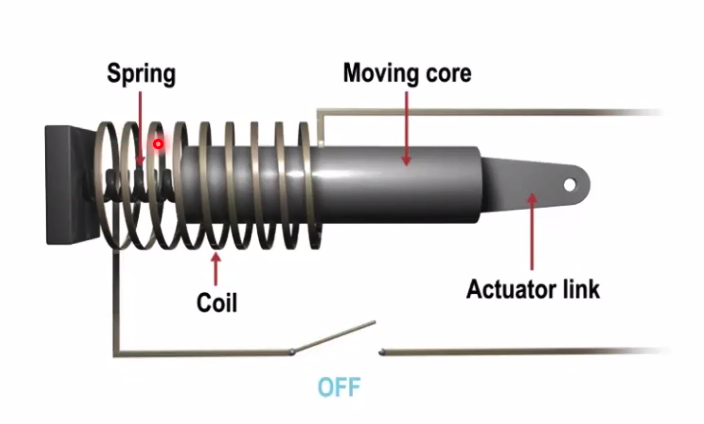
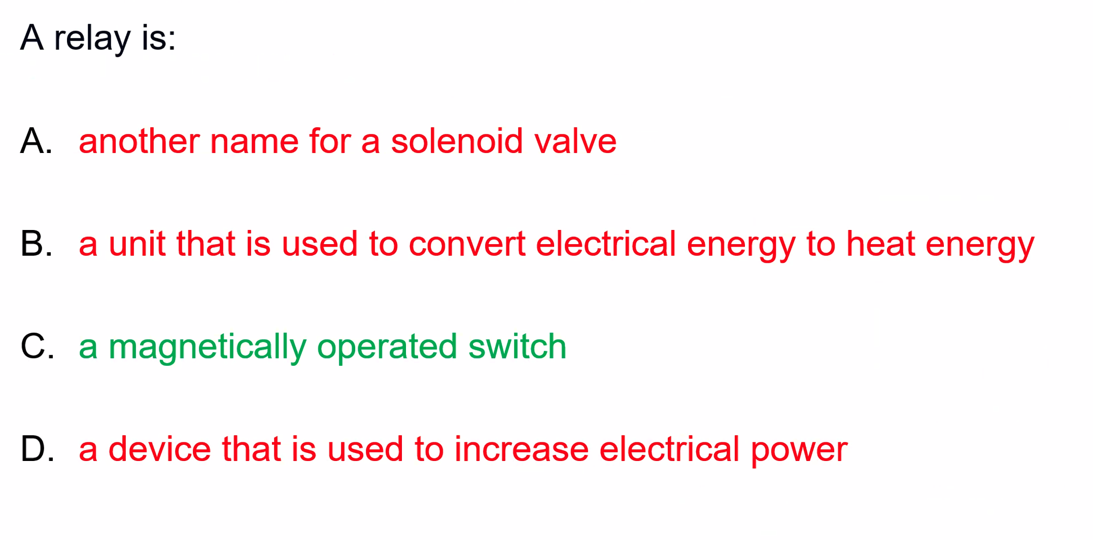
RELAYS
- Remove switching
- Opened or closed by design
- To open or closes circuits. (traditionally used to open close a LT/HT circuit)
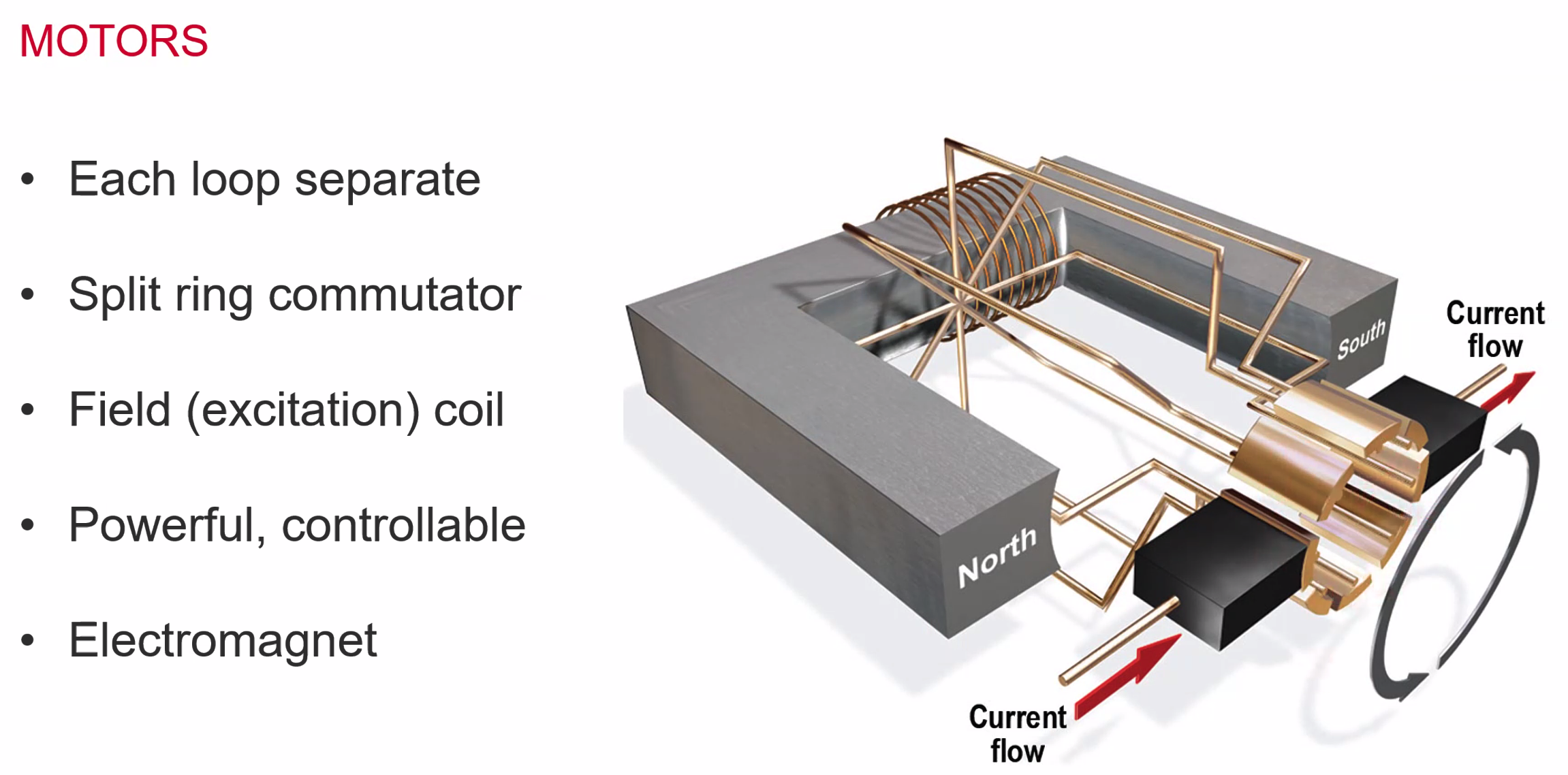
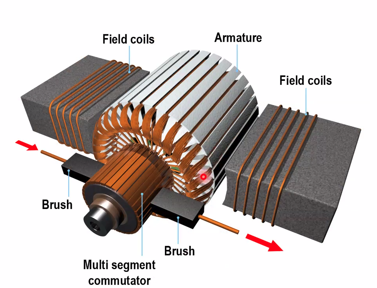
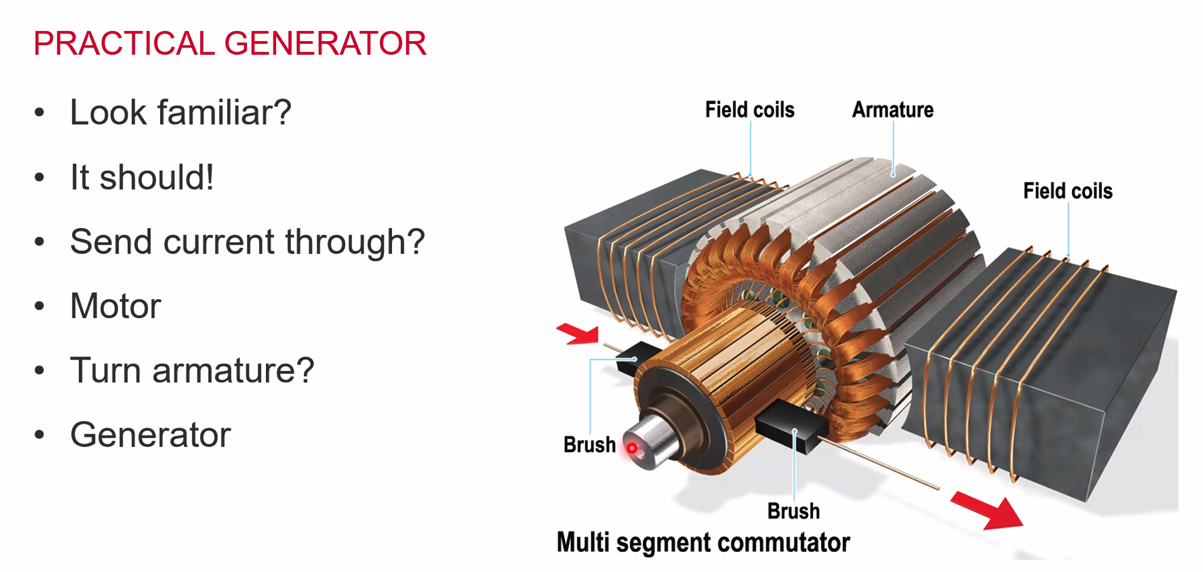
A practical DC Motor
- Lots of loops
- with a multi-segment commutator
- it has powerful field coils
- but how to power it?
Fleminings Left hand rule is for motor
Flemings Right hand rule for generators (or GENERIGHTERS)
Rotary Actuators

- Turns about 350deg
- limit switch stops travel
- split field motor which reverses direction and goes back and forth as needed
- FCS Control actuators
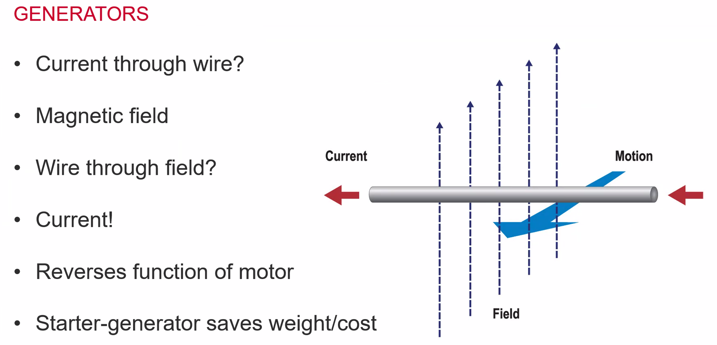
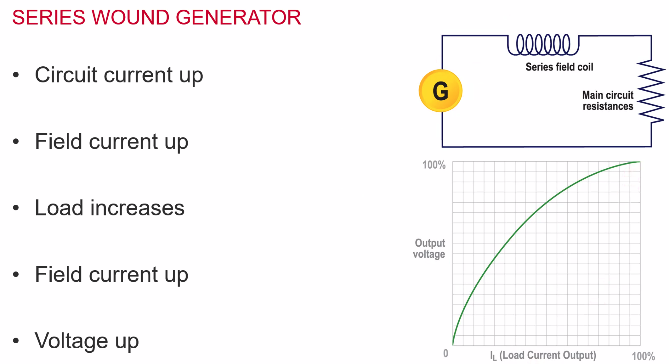
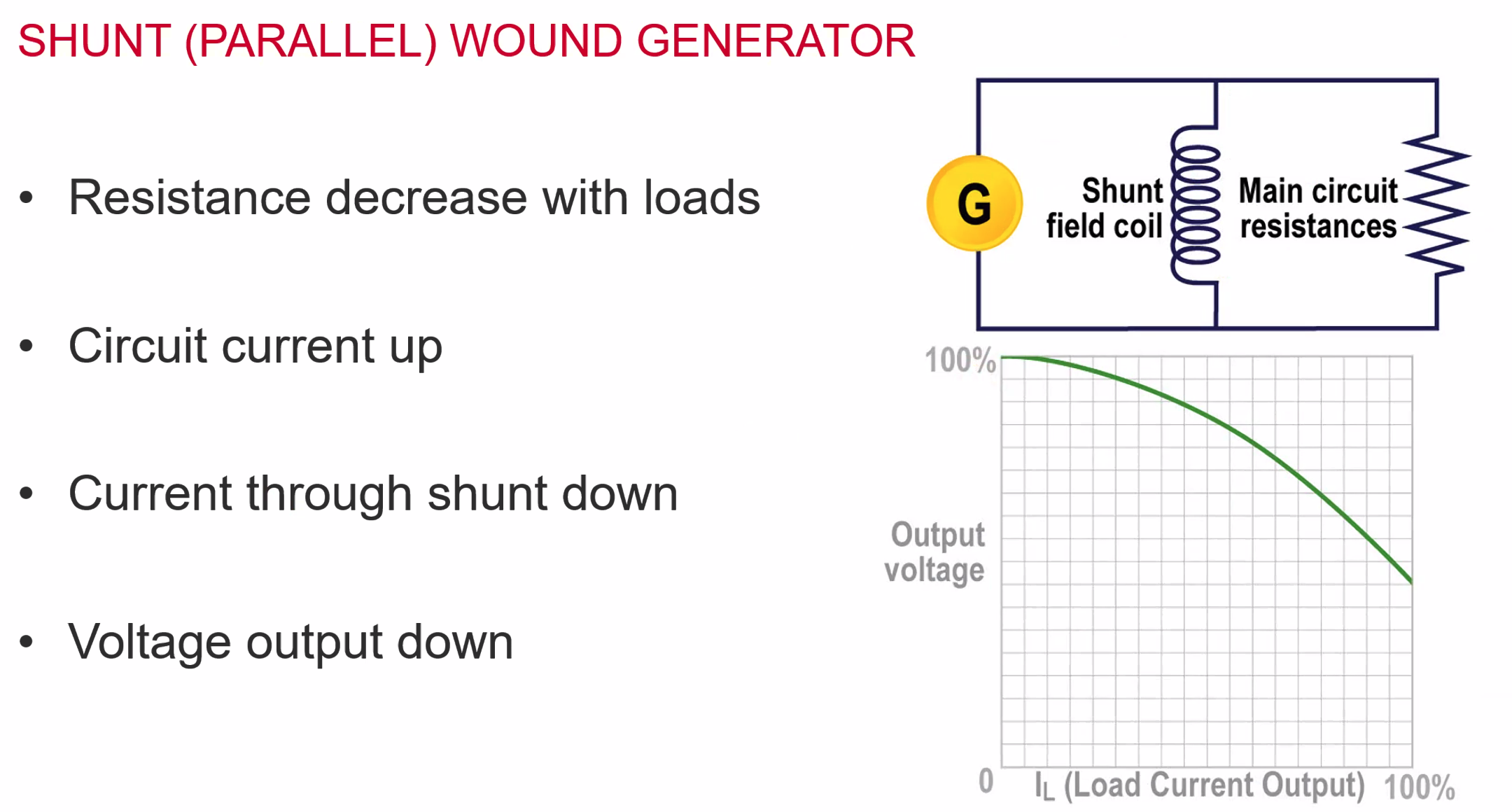
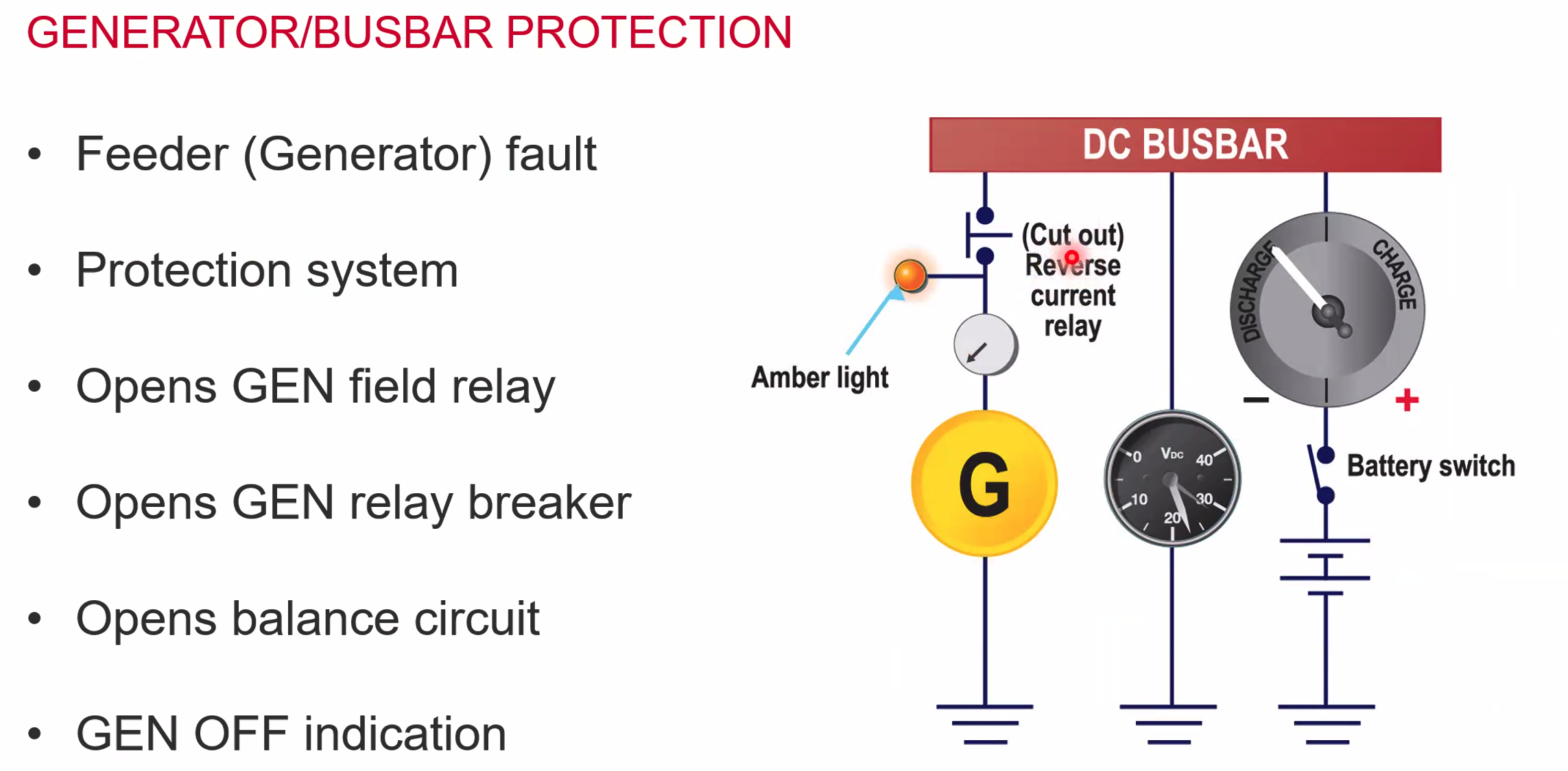
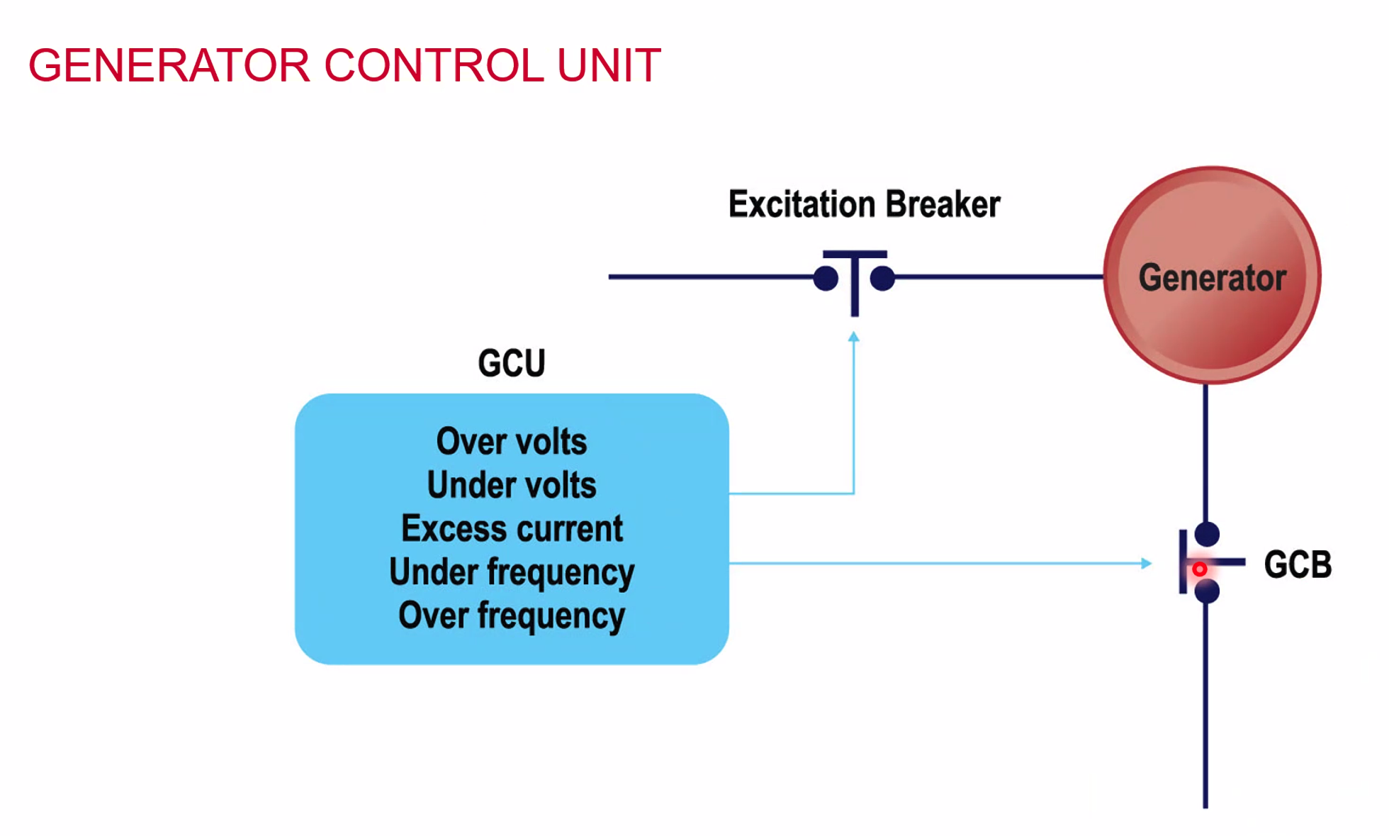
The Cut Out current relay acts as a non return valve - if the generator is producing less current than the Busbar can be provided the cut out relay will disconnect
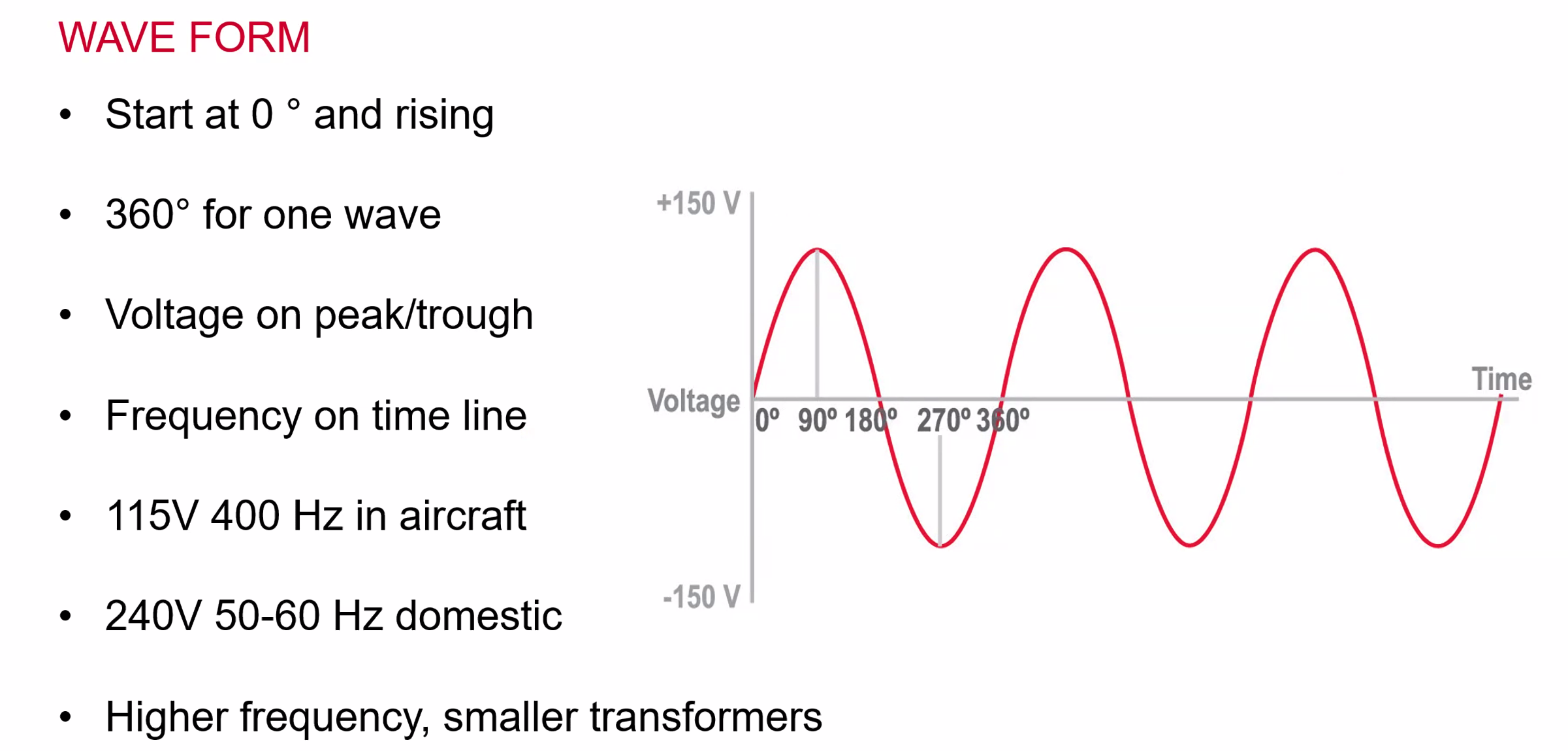
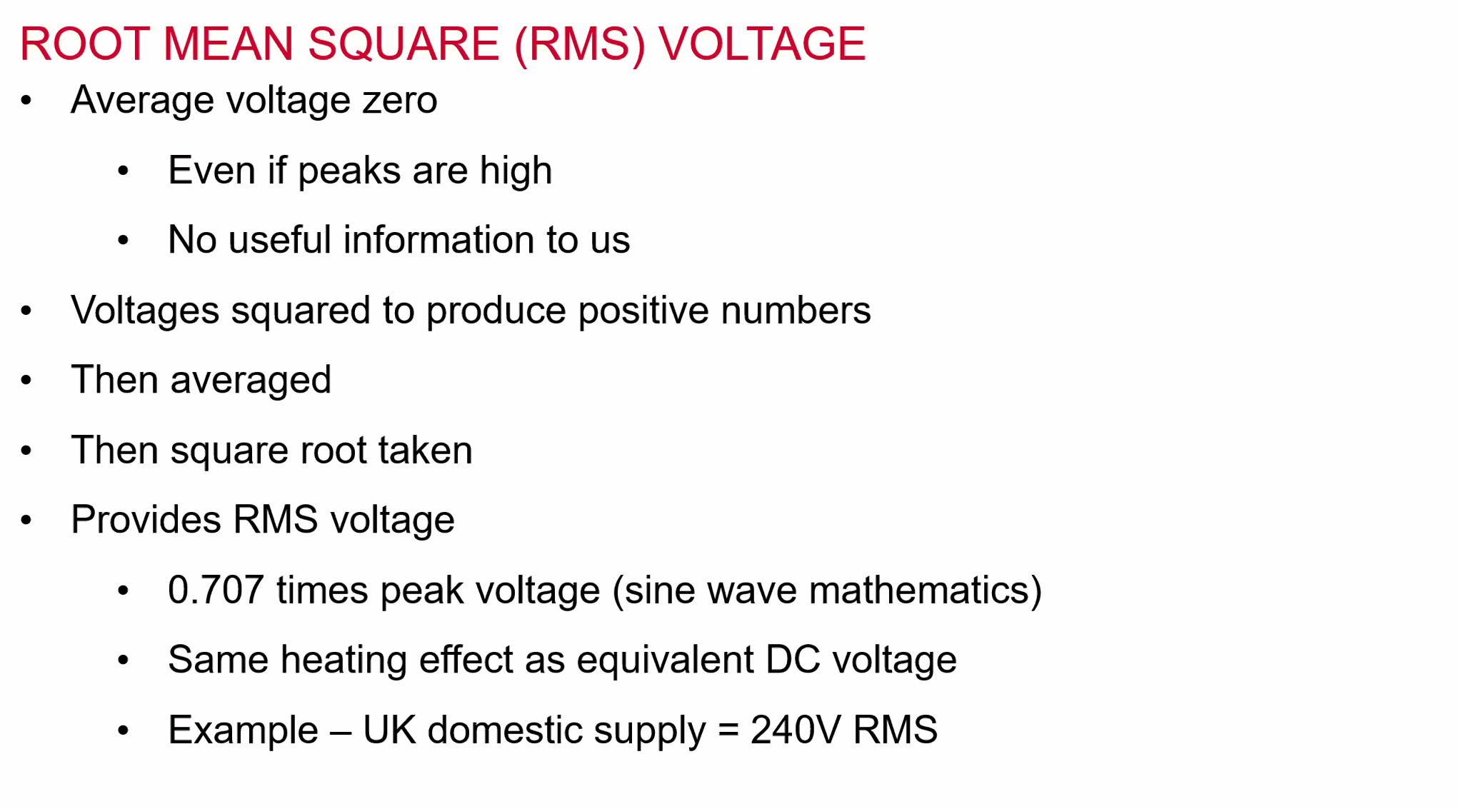
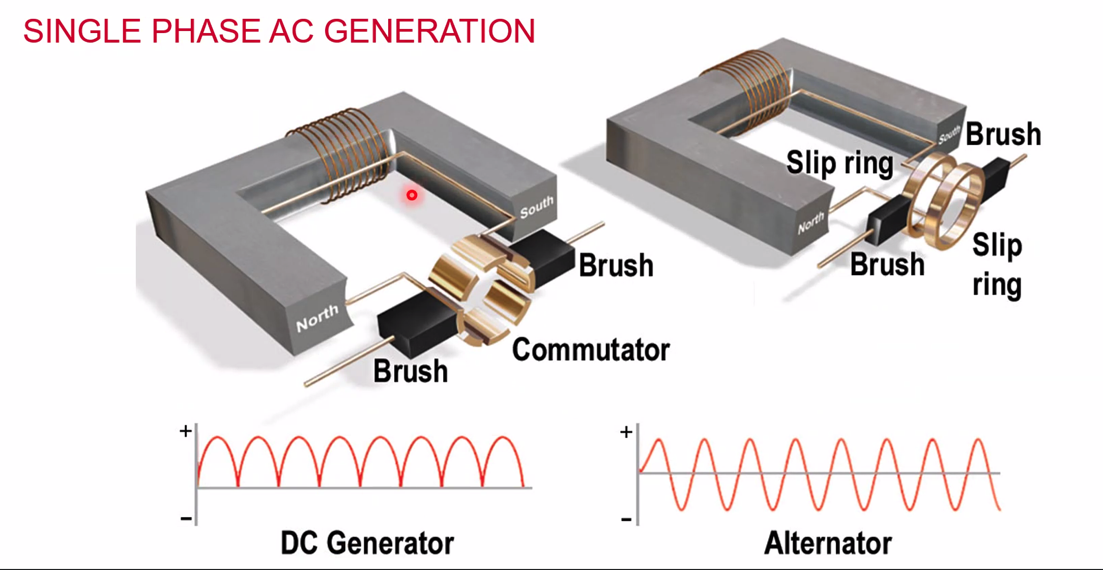
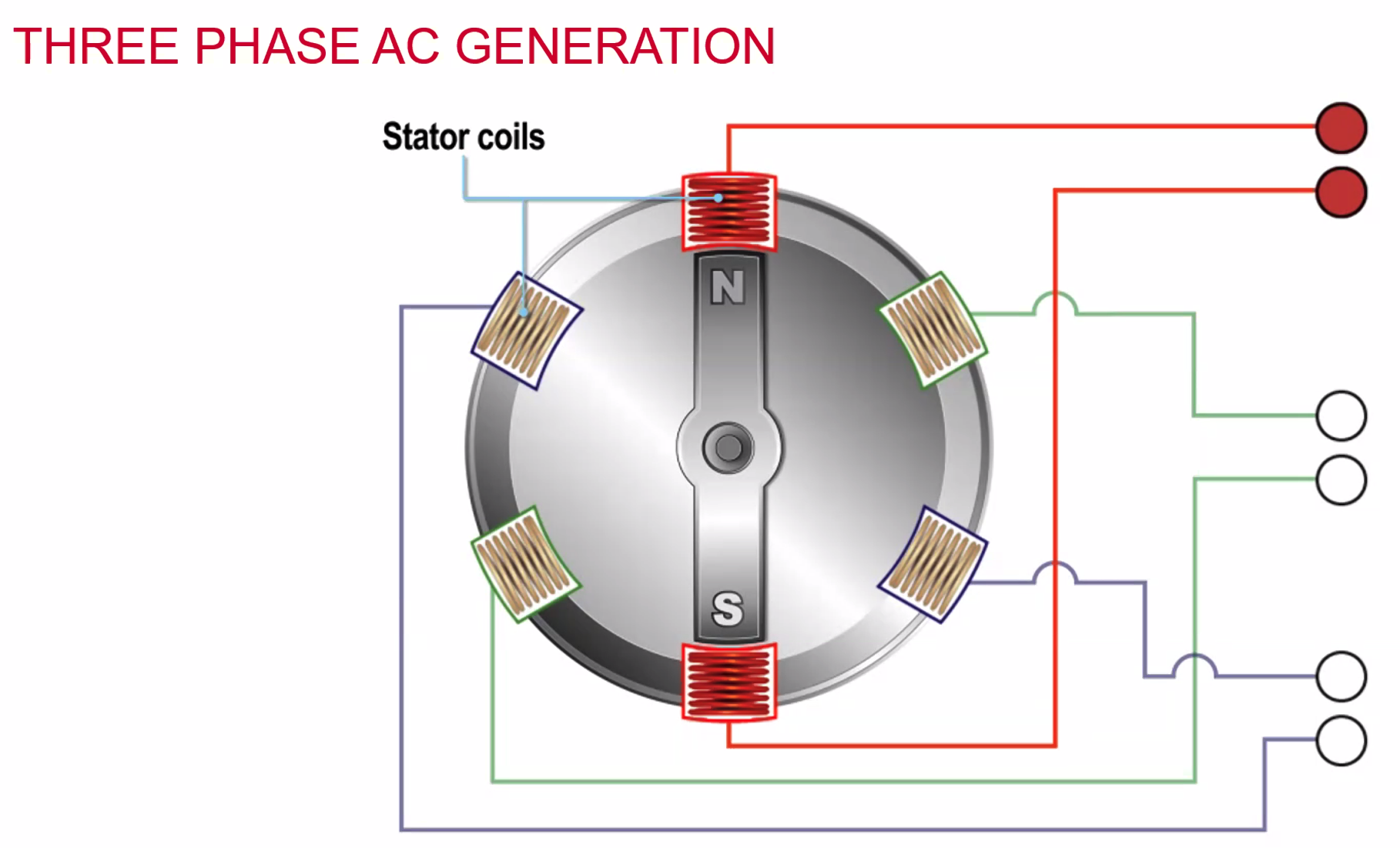
For AC Generation we can either rotate a magnet around coils OR we can rotate the coils around a magnet.
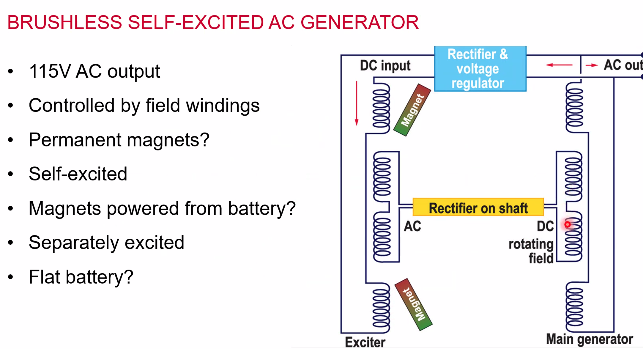 Notice no generator in the above - the DC creates the input to excite the circuit
Advantages of AC Generators:
- Lighter than DC Generators
- Better power to weight ratio
- Easy to change voltage with transformers
- Easy to convert AC to DC if required
- Brushless, so less maintenance
- Product voltage at lower RPM than DC generators
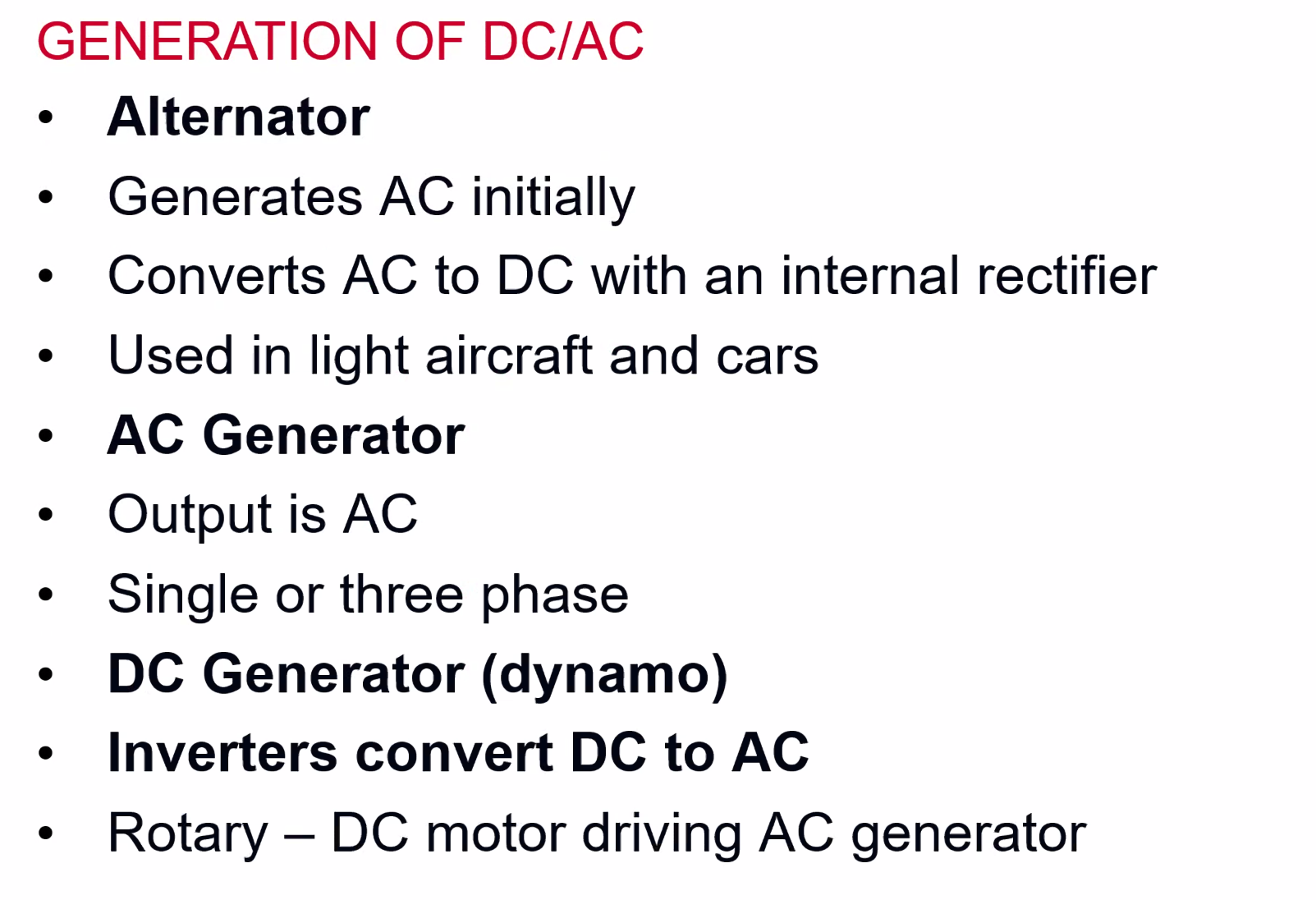
- Most light aircraft use alternators - AC to DC through a rectifier
- Some aircraft use DC starter/generators
- Where primary DC, then AC is supplier through an inverter
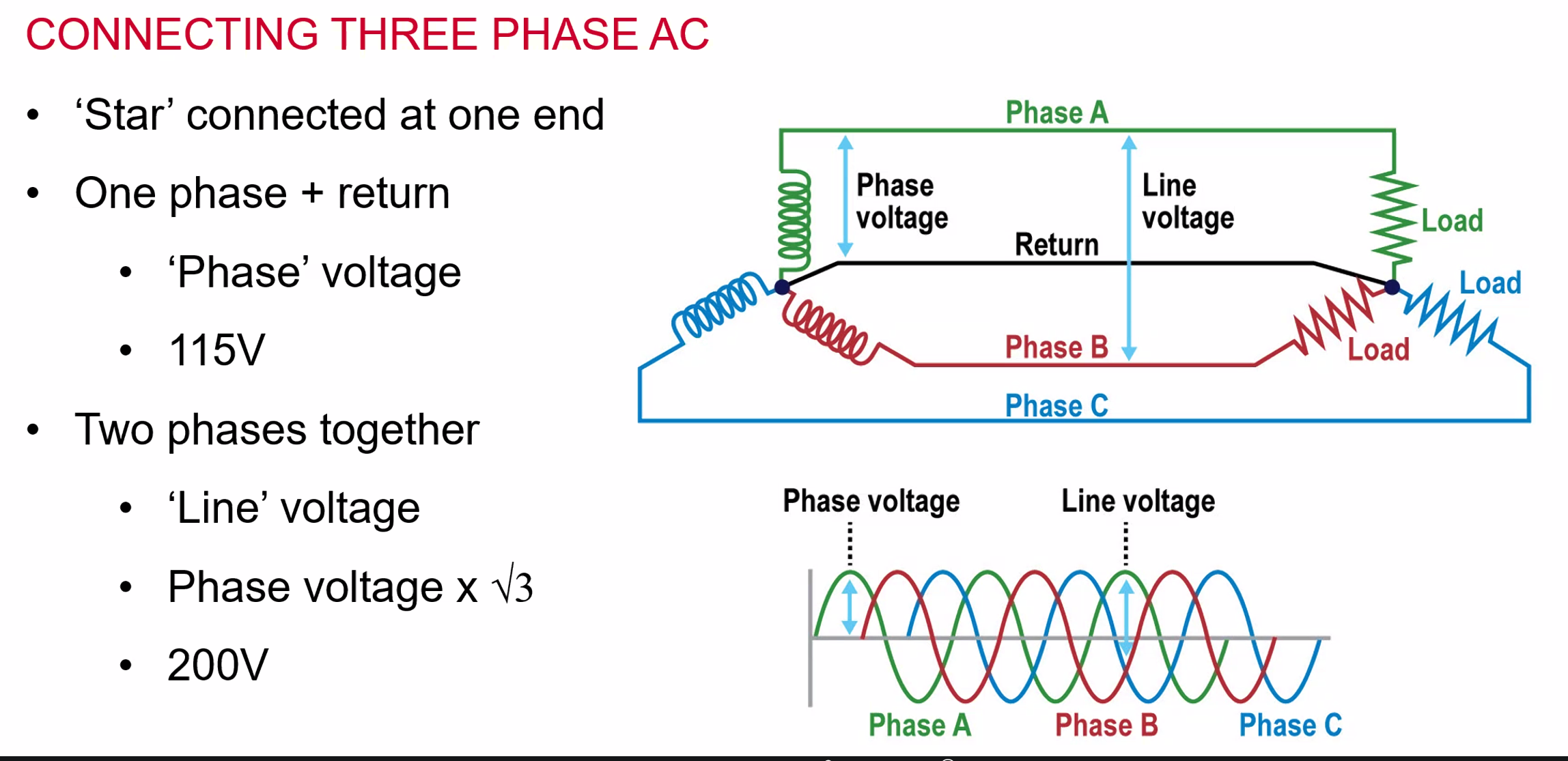
Line and phase current remain the same
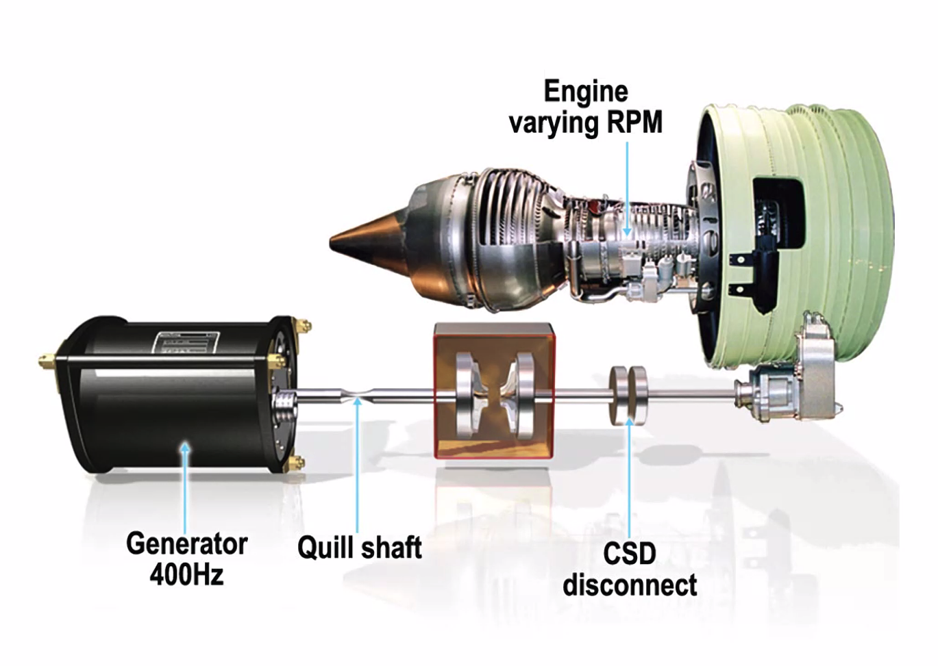
Constant Speed Drive Unit
- Copes with varying RPM
- Hydro-mechanical
- Oil also cools
- Hydraulic Pump (variable)
- Hydraulic Motor (fixed)
- Frequency: 380 - 420 Hz
- 6000 RPM
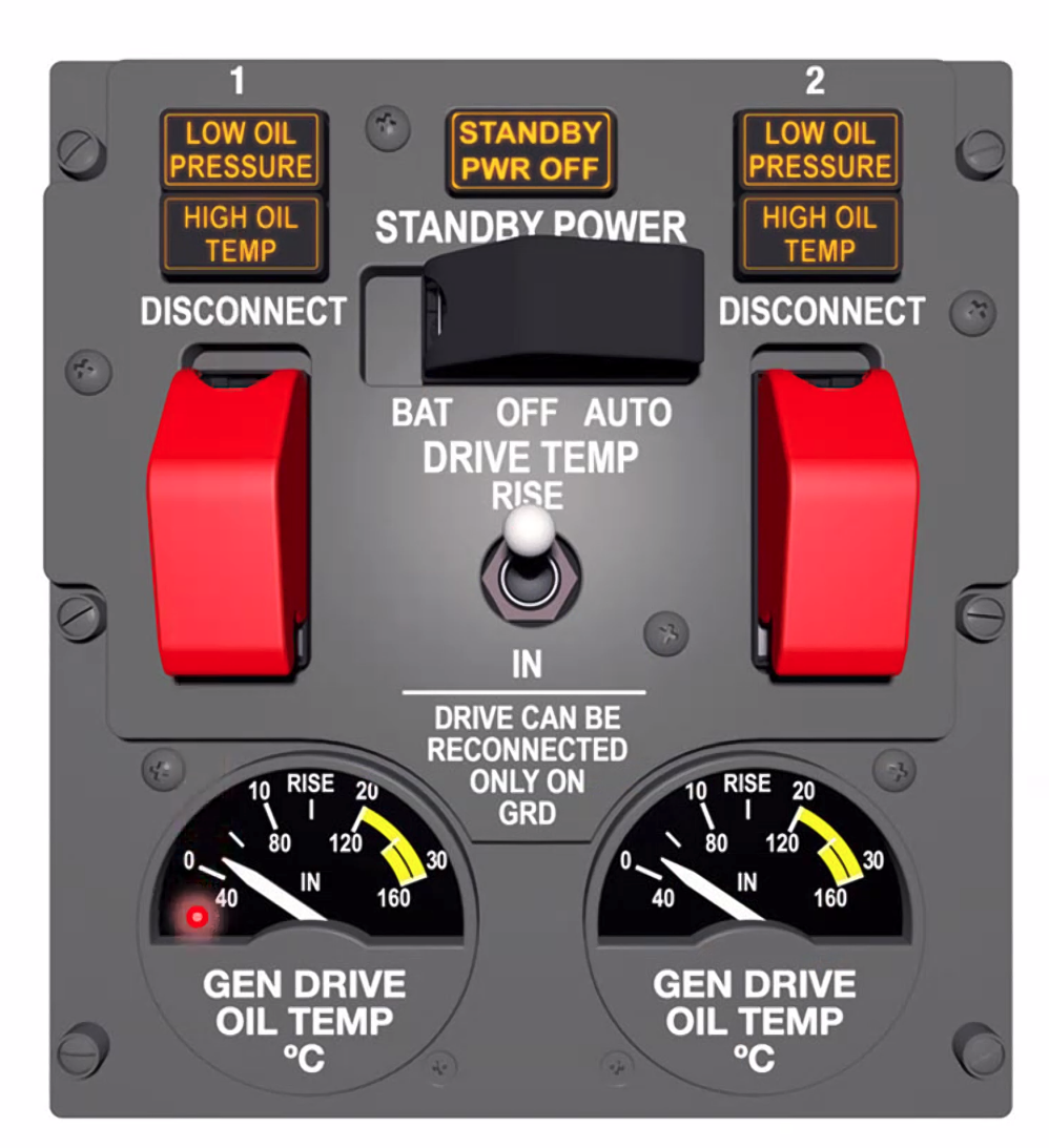
 CSDU Control Panels:
- pressure caption
- temp gauge
- switching off the drive can only be reconnected on the ground.
Transformers
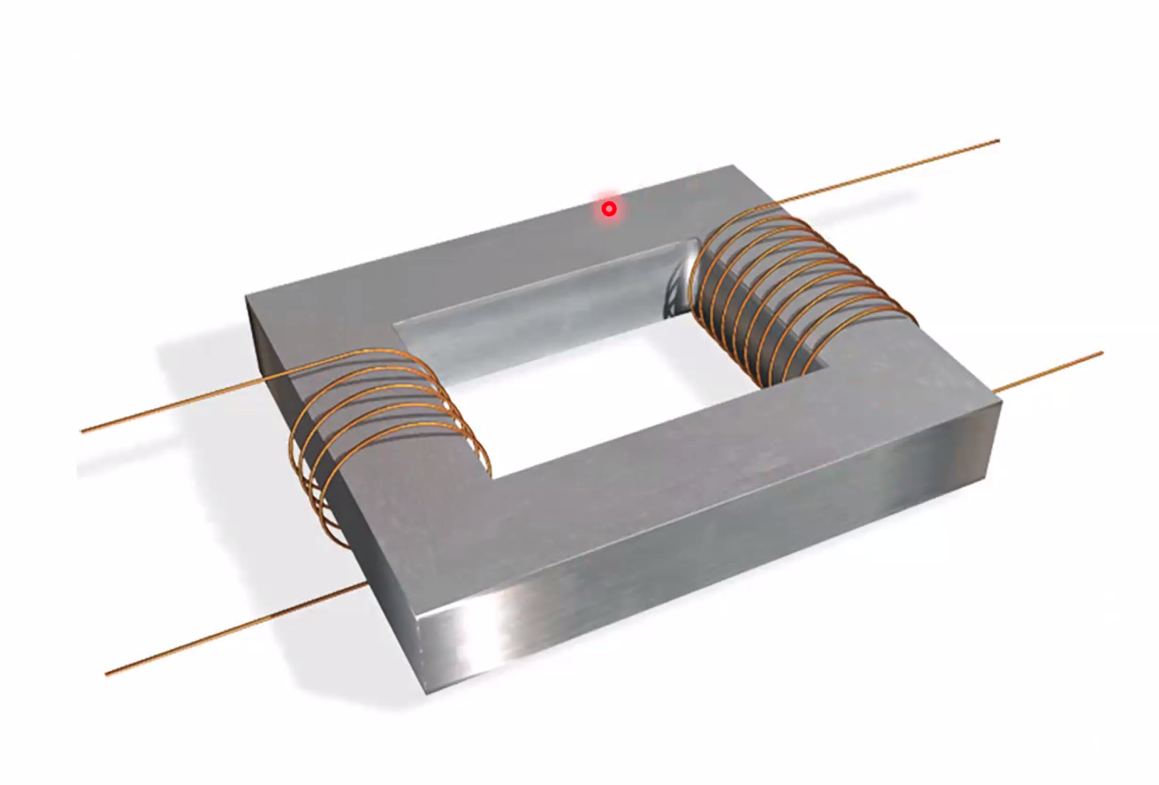
- induce a current to either step up or down the current
- Double the turns? Double the volts and half the currents
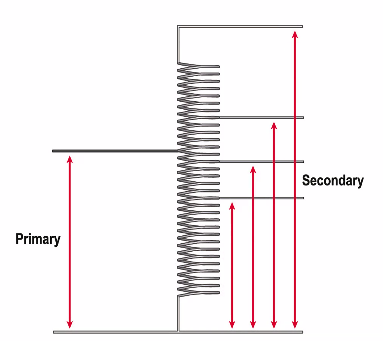
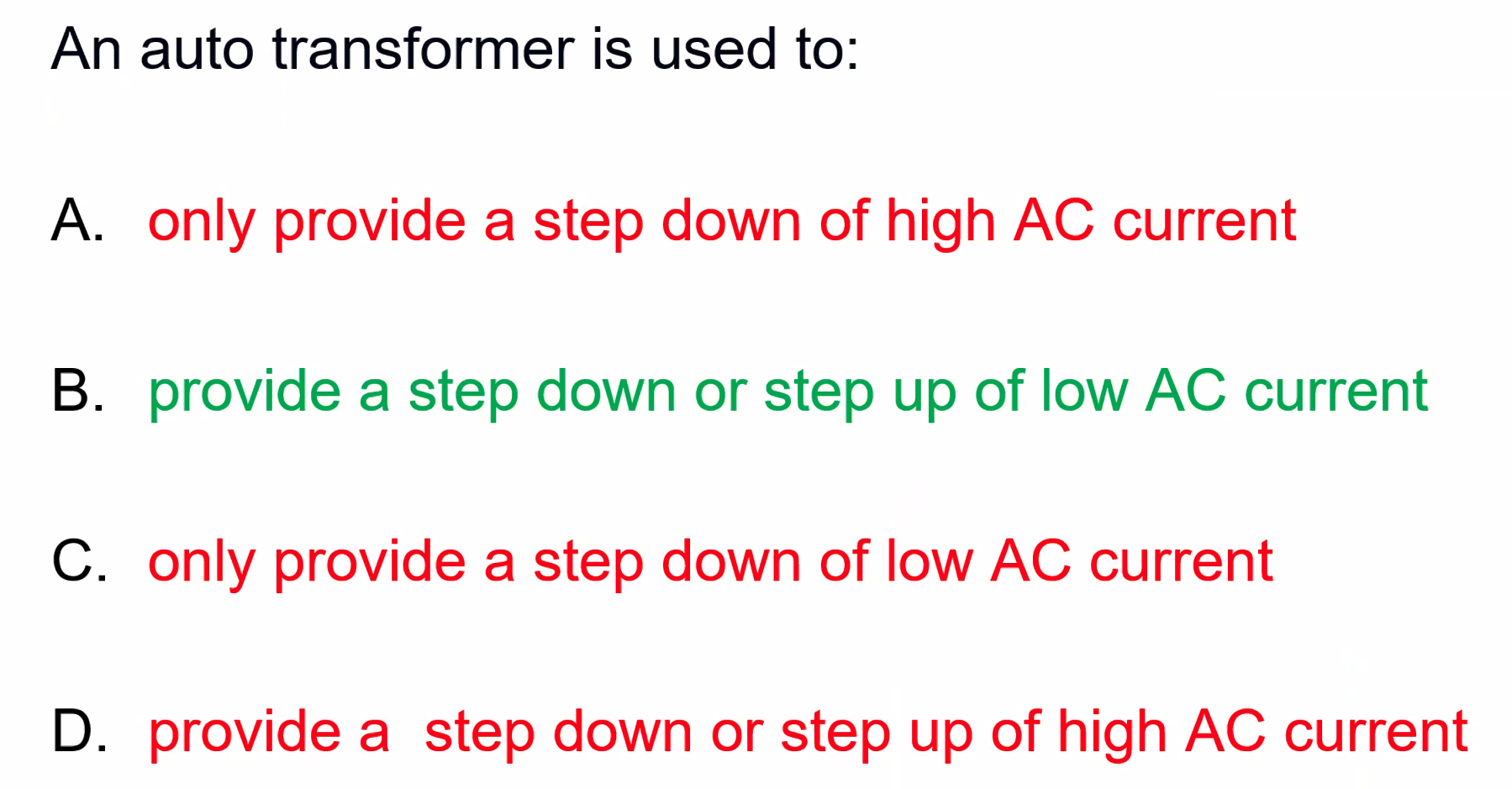
Auto-transformers
- steady input on primary
- You get various output voltages
- used mainly for lighting or low current applications
Rectifiers
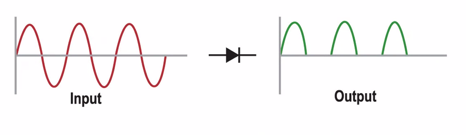
Uses a DIODE (A non return valve for electricity).
Converts AC input into a direct current.
Chops off the negative wave and leaves only the positive wave.
Combination of both of the Rectifiers and transformers.
Transformer Rectifier Unit
- 240V AC Input
- Step down to 14V AC Rectified to DC
- Has the full wave - four diodes
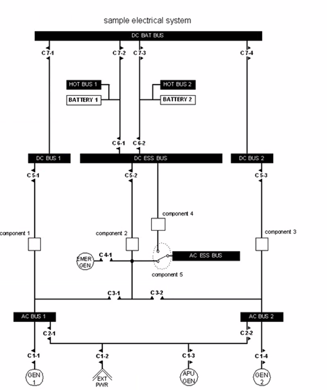
- Components 1, 2 and 3 are TRUs
- Component 4 is a Static Inverter
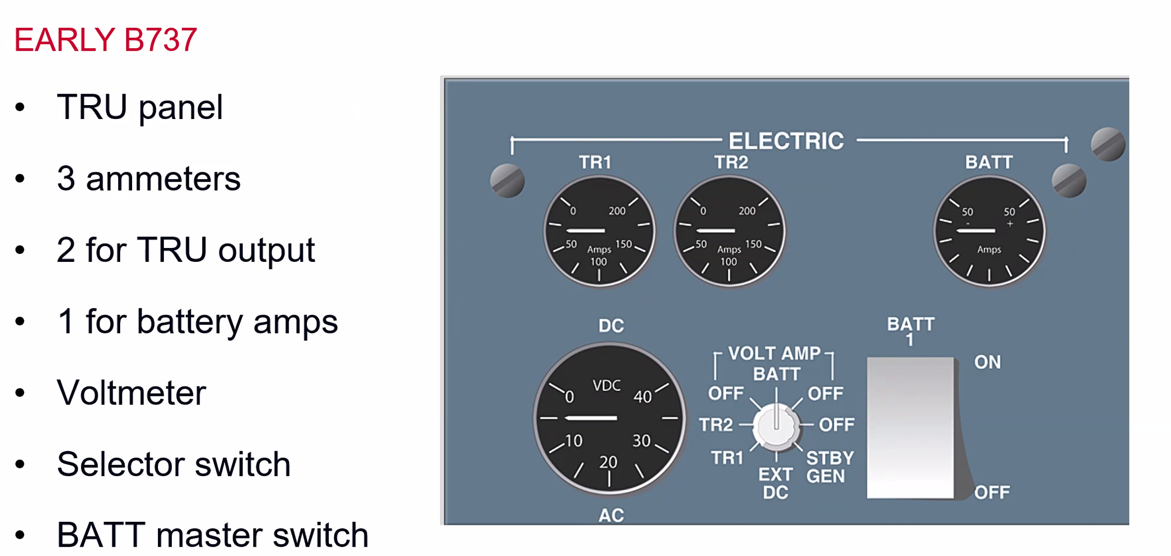
- Also a Static Motor, which works off of the principles of PFM / Solid State
Engines
Internal Combustion
- Piston Engine
- Gas Turbine
- Both convert chemical energy into a heat energy by burning fuel
Boyles Law
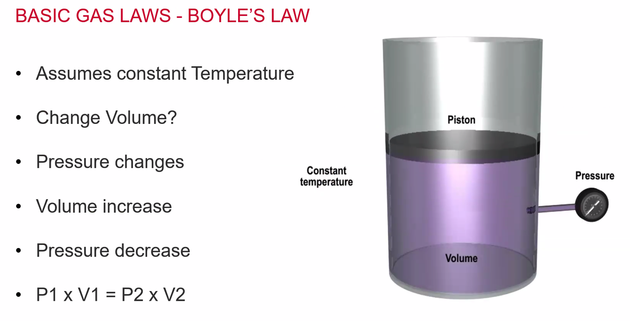
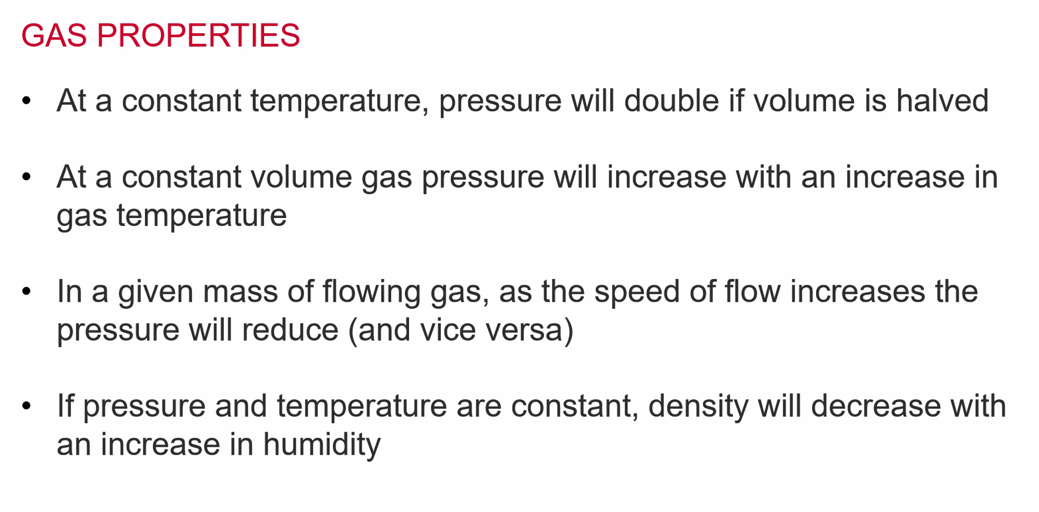
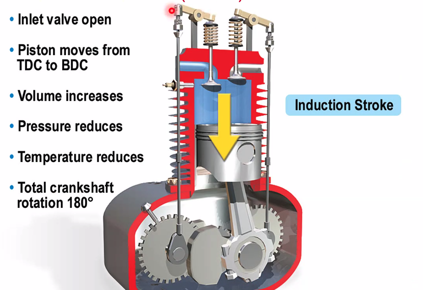
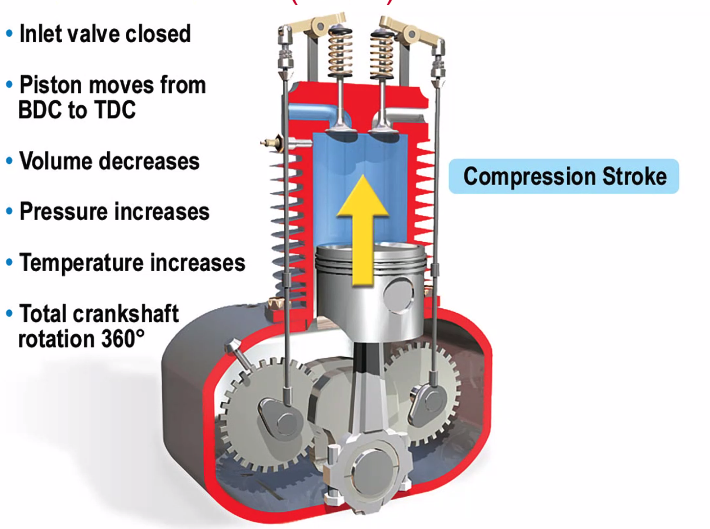
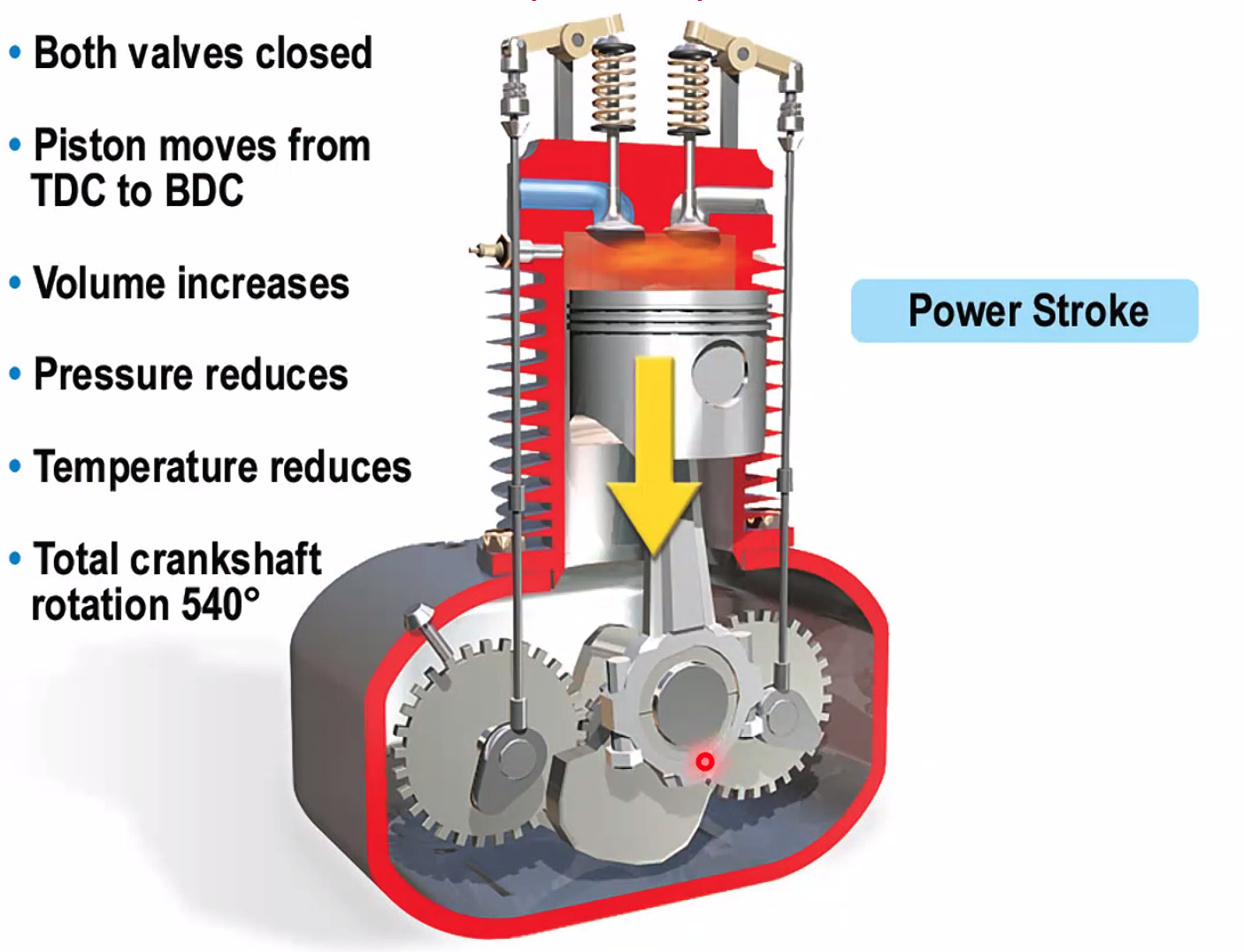
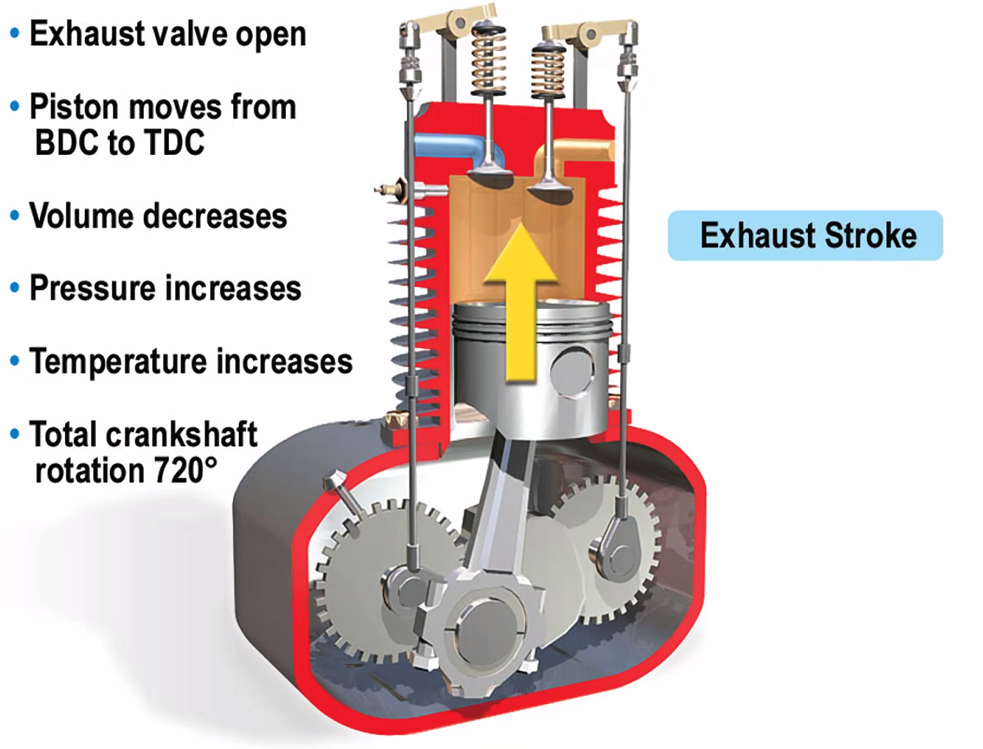
Volume increases? pressure decreases. Assumes a constant temperature.
P1 x V1 = P2 x V2
Charles Law
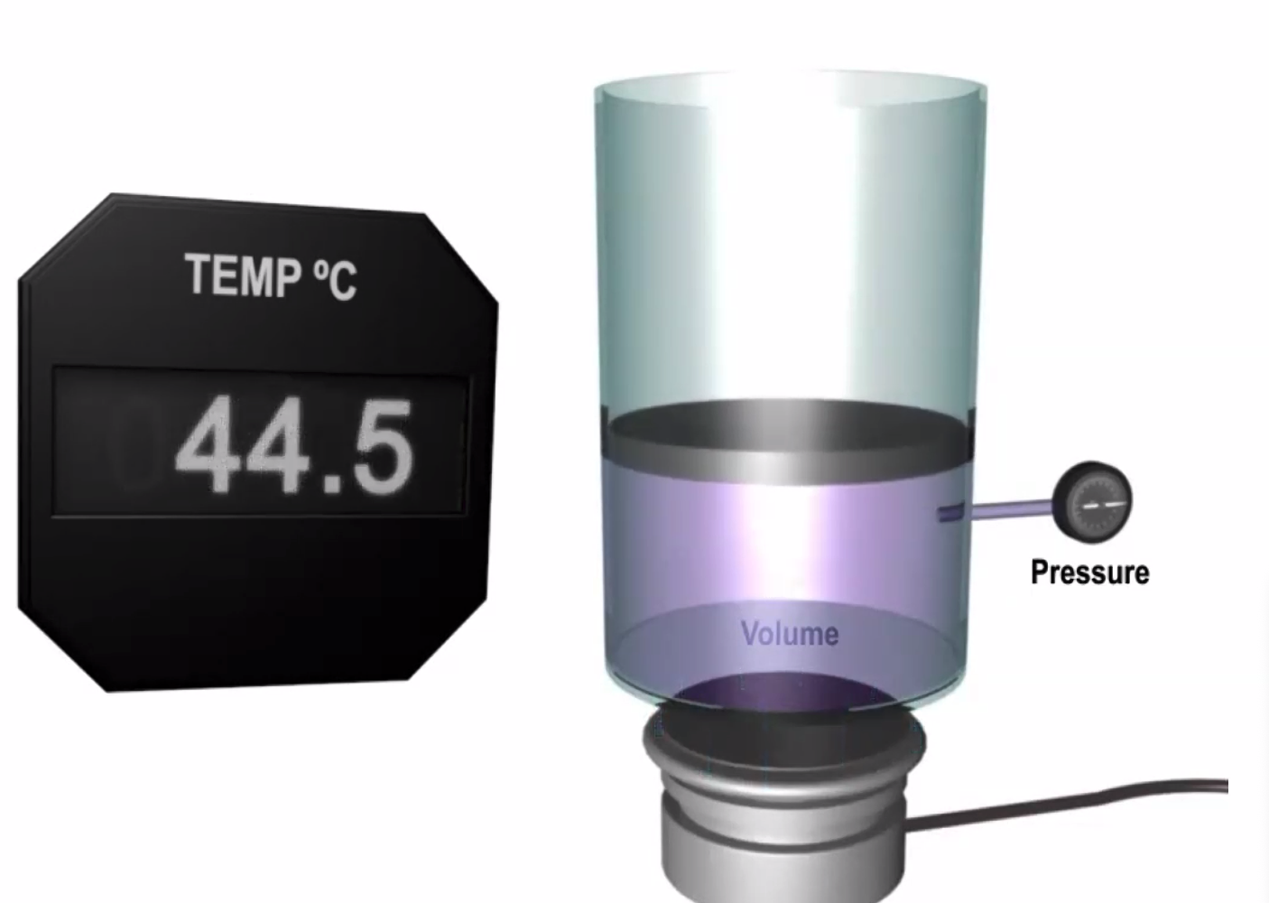
In a Constant Pressure with a changing of temperature? Temperature increases, volume increases. Essentially the initial workings of why a hot air balloon works.
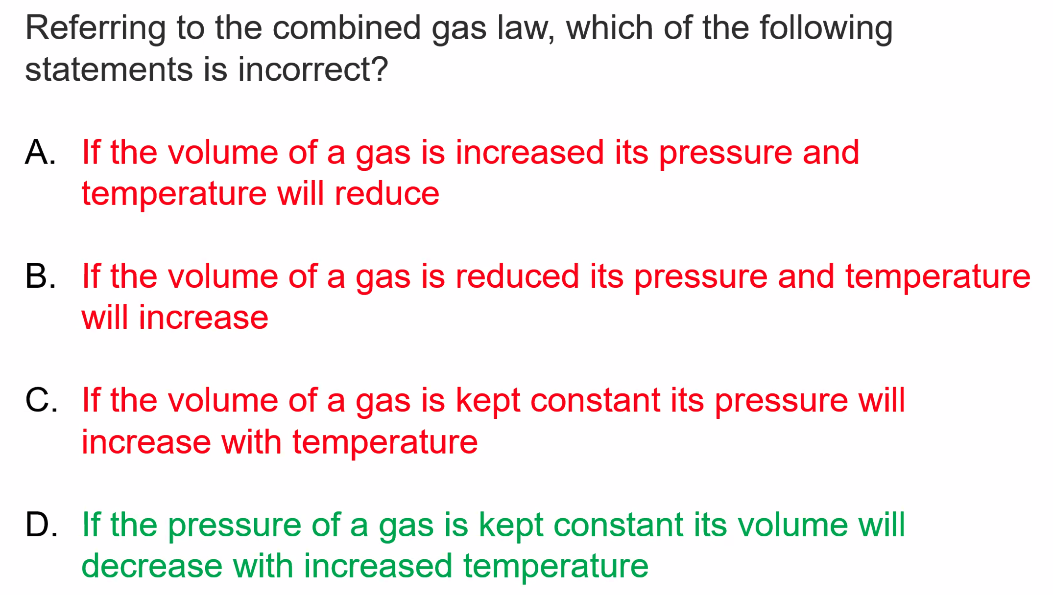
Combined Gas Law - combination of Charles and Boyles Law
If the volume of a gas is kept constant, its pressure will increase with temperature. If the volume of a gas is reduced, its pressure and temperature will increase. If the volume of has is increased, the pressure and temperature will reduce.
If the pressure of the gas is kept constant, its volume will increase with temperature
Pressure x Volume / Temperature = Constant
OR
PV / T = K
Heat Transfer
- Conduction
- Direct transfer, molecule to molecule - putting your hand on the stove
- Convection
- Circulation of warm gas or liquid, think oven
- Radiation
- Electromagnetic Waves absorbed by another body - think solar radiation / insolation
Newton’s Laws of Motion
- First Law - a body will continue in a state of rest or uniform motion in a straight line unless acted on by an external force
- Second Law - The rate of change of momentum is proportional to, and takes place in the direction of, the applied force
- Third Law - Action and reaction are equal and opposite
Definitions
Mass - amount of matter in a body Inertia - opposes change in motion Force - influence that causes a body to move
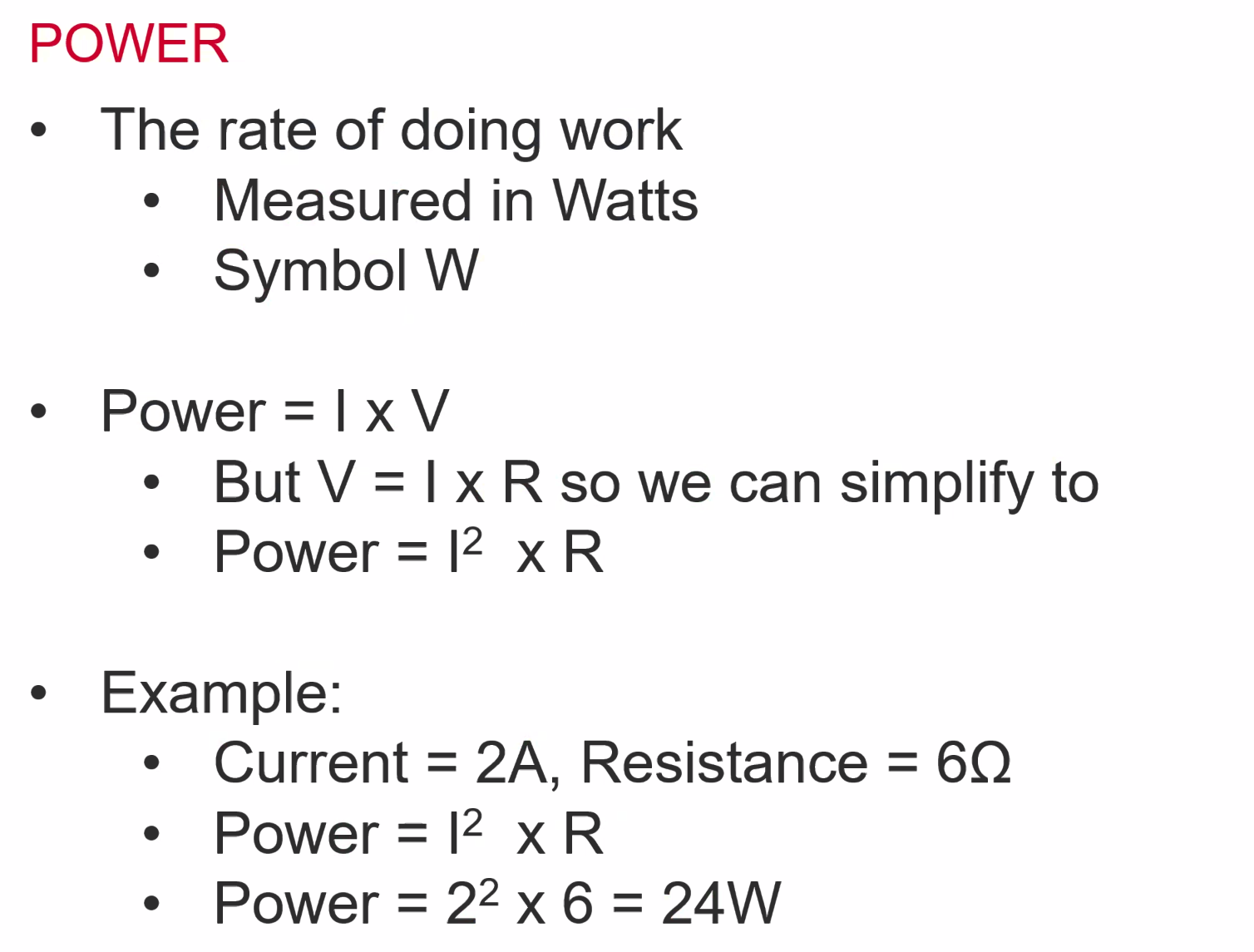
Work - the product of the force and the distance
Work = Force x Distance
1 joule - 1 N moves an object 1M
Power = Force x Distance / Time
Watt = 1 joule per second
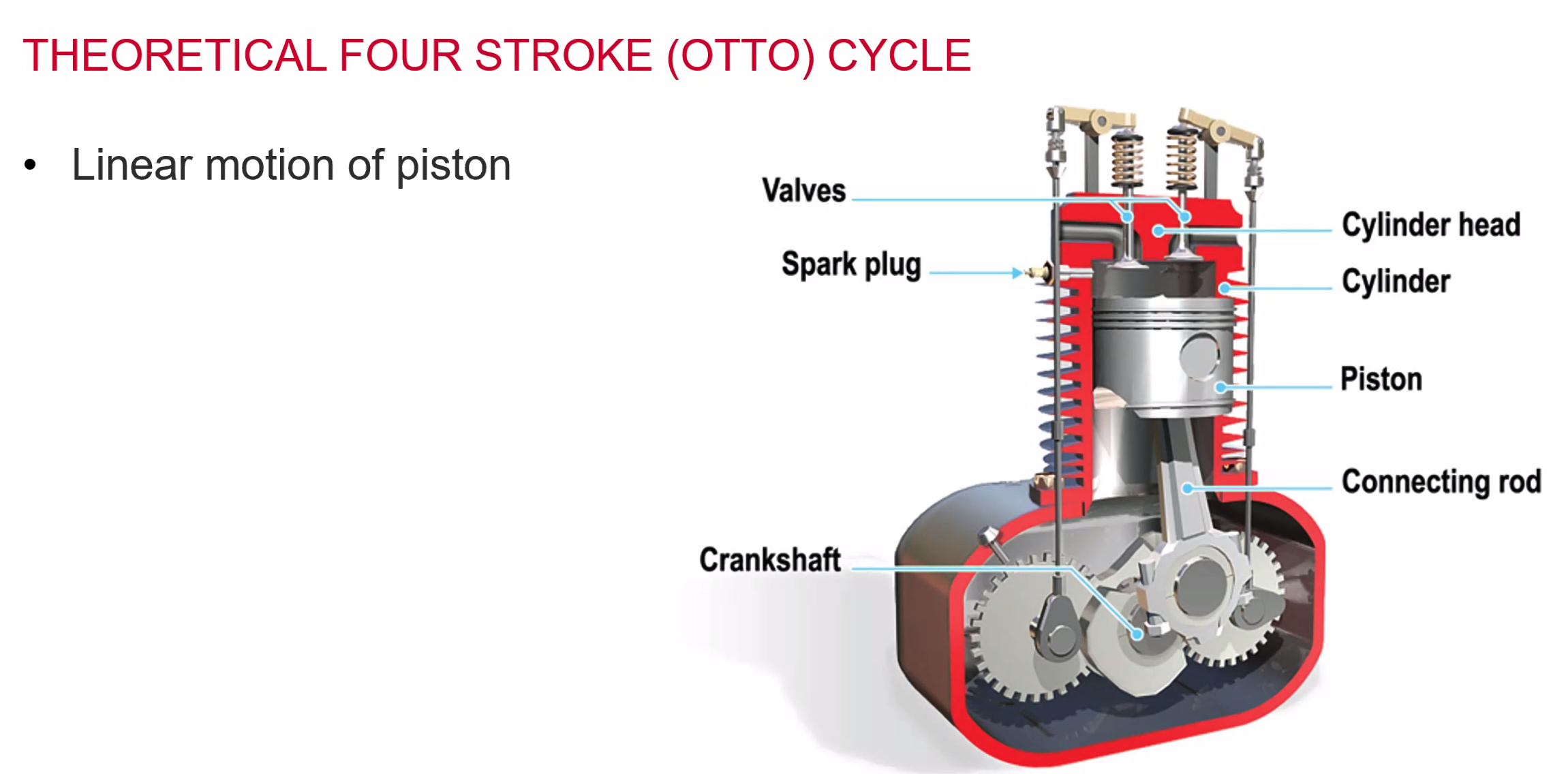
- The linear motion of the piston is converted to Rotary motion through the crankshaft. Which is connected by a connection rod.
- Spark plugs ignite the mixture - we want combustion and not explosion.
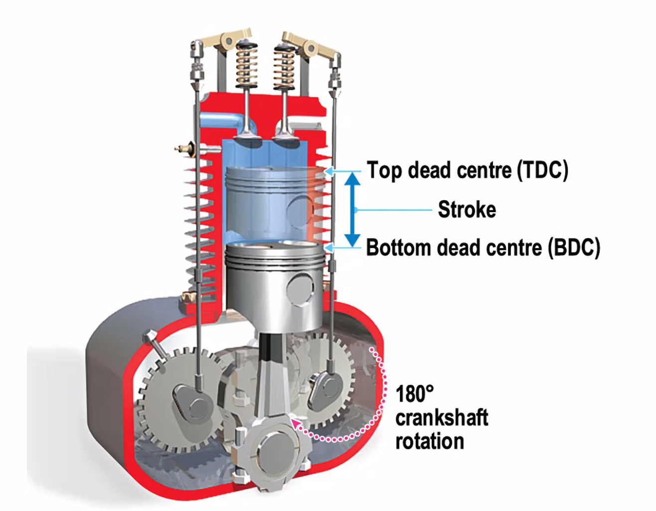
Top Dead Centre
Bottom Dead Centre
 ![[CleanShot 2026-07-08 at 08.31.13@2x.png]]

![[CleanShot 2026-07-08 at 08.33.00@2x.png]]

![[CleanShot 2026-07-08 at 08.33.27@2x.png]]

![[CleanShot 2026-07-08 at 08.38.22@2x.png]]

![[CleanShot 2026-07-08 at 08.43.30@2x.png]]

![[CleanShot 2026-07-08 at 08.44.46@2x.png]]

![[CleanShot 2026-07-08 at 08.51.59@2x.png]]

![[CleanShot 2026-07-08 at 08.54.12@2x.png]]

![[CleanShot 2026-07-08 at 08.55.10@2x.png]]

![[CleanShot 2026-07-08 at 09.01.36@2x.png]]

![[CleanShot 2026-07-08 at 09.03.35@2x.png]]

![[CleanShot 2026-07-08 at 10.31.09@2x.png]]

![[CleanShot 2026-07-08 at 10.53.29@2x.png]] ![[CleanShot 2026-07-08 at 10.54.44@2x.png]]


- Look for the up and the down in the sentence or a down and an up
![[CleanShot 2026-07-08 at 10.56.12@2x.png]]

In this question there is not a Down and an up or an up and a down so everything is false
![[CleanShot 2026-07-08 at 11.21.56@2x.png]]

https://www.youtube.com/watch?v=0bP2MH3LqvI&t=103s
![[CleanShot 2026-07-08 at 11.48.10@2x.png]]

![[CleanShot 2026-07-08 at 11.48.58@2x.png]]

![[CleanShot 2026-07-08 at 11.52.04@2x.png]]
