Andy / andy@bristol.gs
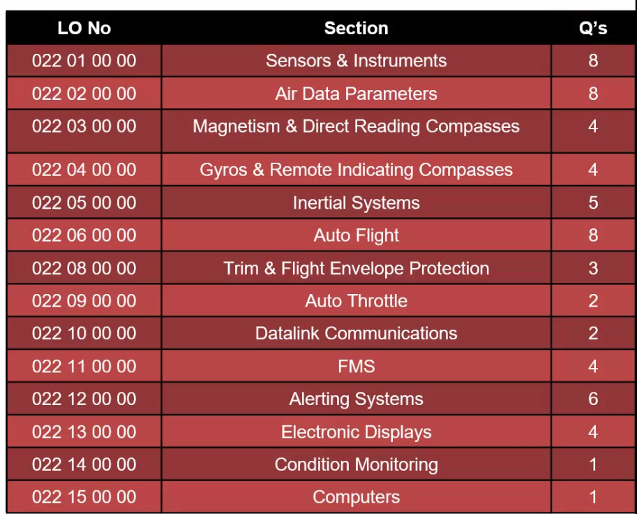
60 Questions - 1hour 30 mins
Temperature
Celsius and Kelvin 100C - 373K 0C - 273K -273C - 0K
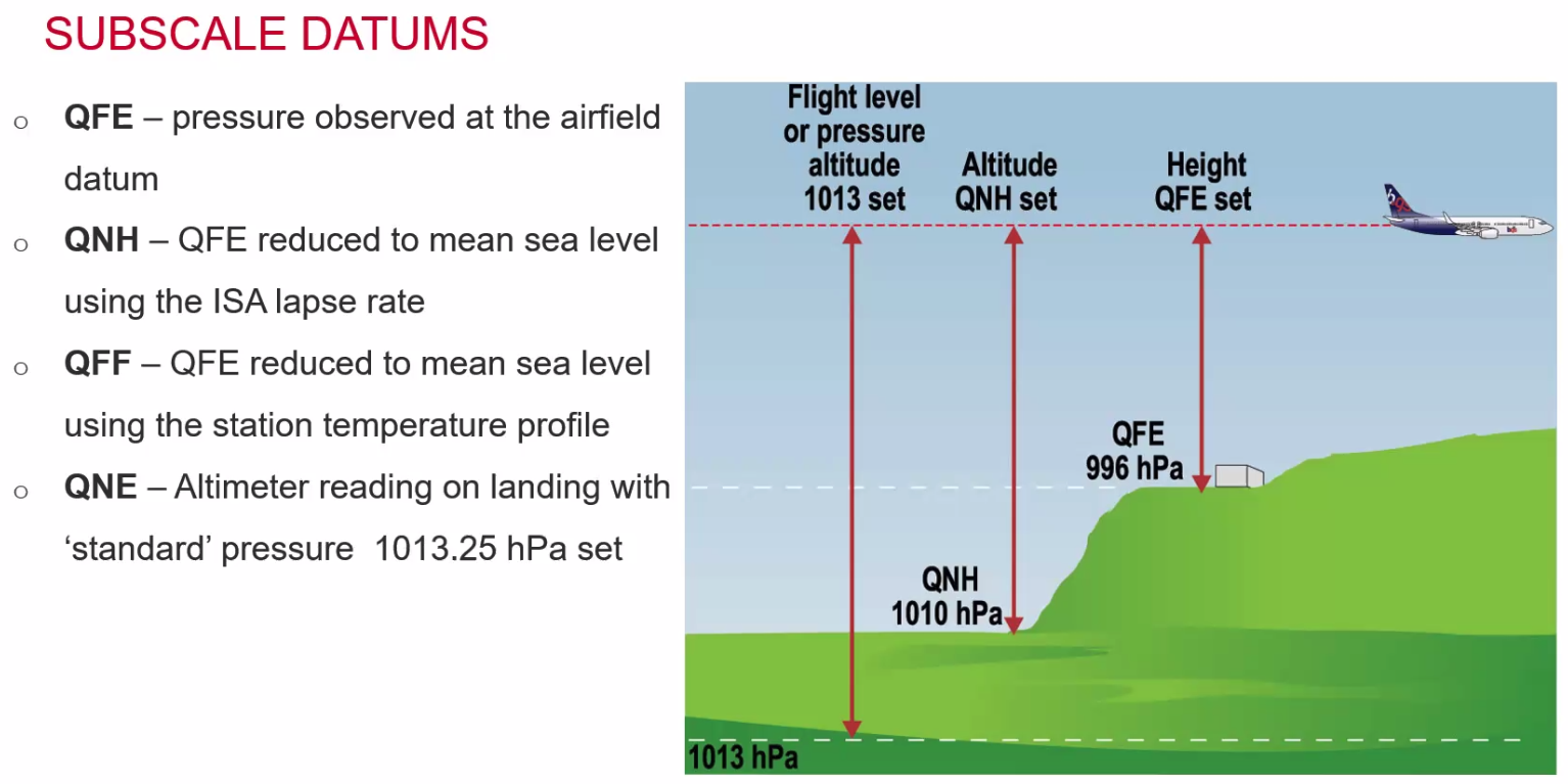
Datums points of:
- 0F at the freezing point of salt water and;
- 100F at the average temperature of the human body
On the Fahrenheit scale:
- Salt water freezes at 0F
- Fresh water freezes at 32F
- Fresh water boils at 212F
==Q. What is 9C expressed in Fahrenheit?== Formula: F = C x 9 / 5 + 32 OR use the CRP5 A. 48.2F
Temperature sensing in aviation
- Mercury Thermometer - corrosive to airframes, not used much
- Bimetallic Sensors
- Resistance thermometers
- thermocouples
Static Air Temperature and Total Air Temperature
- total is dynamic temperature plus the static temperature. It is the SENSED temperature
- Static Air Temp is the real air temp
- Difference is caused by compression (ram rise) and friction
- TAT = SAT + Ram Rise in Temp.
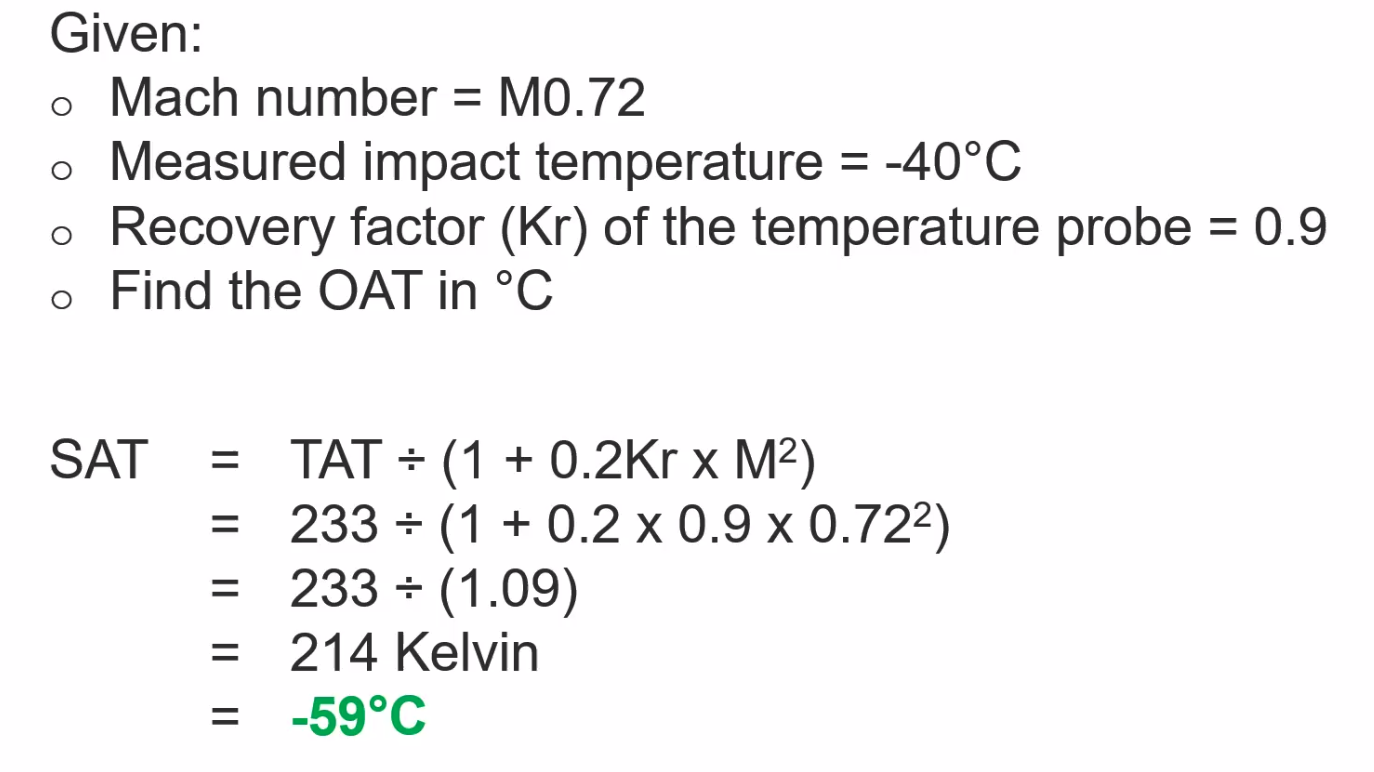
TAT = SAT (1 + 0.2 Kr x M2) Needs to be done in KELVIN!
==TAT will always be the same as OR higher than the SAT.==
==Q. Given M0.72, Measured impact Temp: -40C, Recovery factor (KR) = 0.9, What is the OAT?== A. -59C
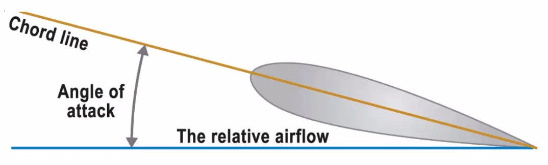
Angle of Attack - angle of the chordline (alpha) to the relative airflow
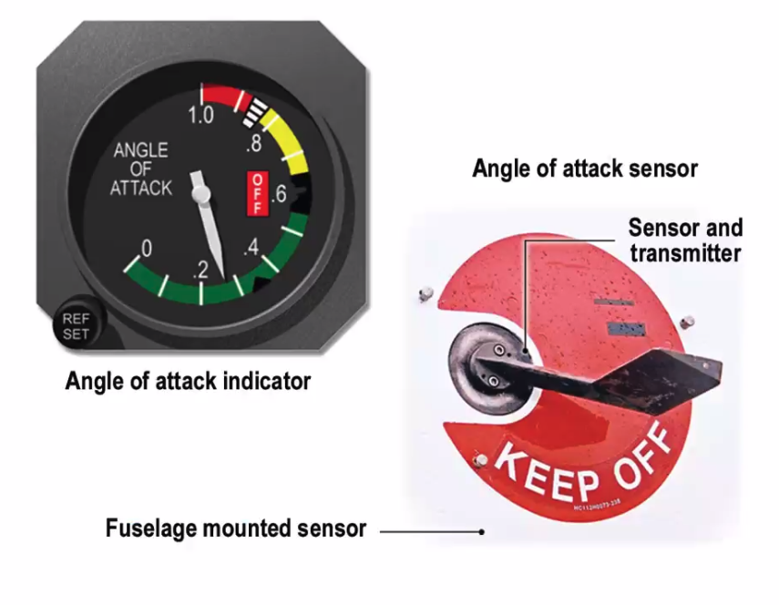
AoA - Vane Sensor
- vane is kept in place by the relative airflow but it is free to rate in airflow.
- Electrically anti-iced.
- Sends angle signal to indicator
- Analogue
 ==Q. At what angle will the Vane sensor be at the 6 hour time in flight, compared to the 2 hour point?==
A. further down, because the aircraft has lost weight and will require a greater AoA
==Q. At what angle will the Vane sensor be at the 6 hour time in flight, compared to the 2 hour point?==
A. further down, because the aircraft has lost weight and will require a greater AoA
AoA - Airflow direction detector
- aka conical slotted probe
- electrically anti-iced
- rotates with the airflow
- indicates on flight deck
==Q. What will be the angle of the airflow director in a climb?==
A. C
AoA - Specific slaved pitot probe
- indicates differential pressure
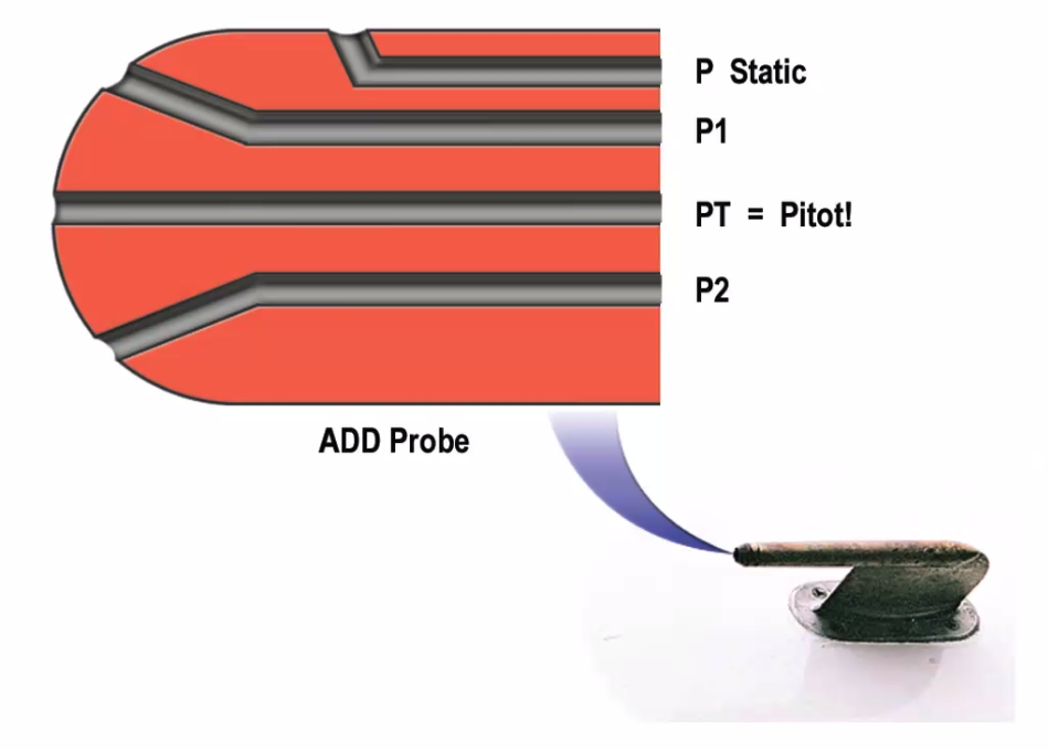
Total (pitot) pressure = static pressure + dynamic pressure
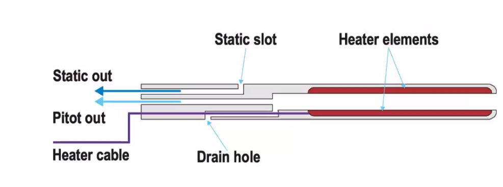
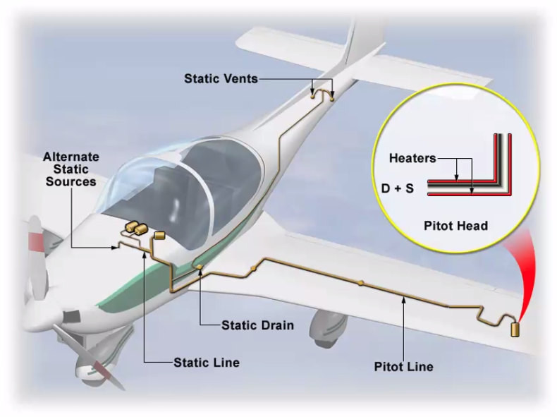
Pitot Tube
- total pressure goes in
- mounted away from boundary layer
- electrically anti-iced
- May include static measurement
- Multi probes on large aircraft
Combination Pitot / Static Probe
- Electrically anti-iced
- Pitot angled for best PEC
- Static minimising dynamic reading
- Could still freeze behind heater
 ==Q. The pitot tube is attached to a mast as to:==
A. to locate it outside the boundary layer
==Q. The pitot tube is attached to a mast as to:==
A. to locate it outside the boundary layer
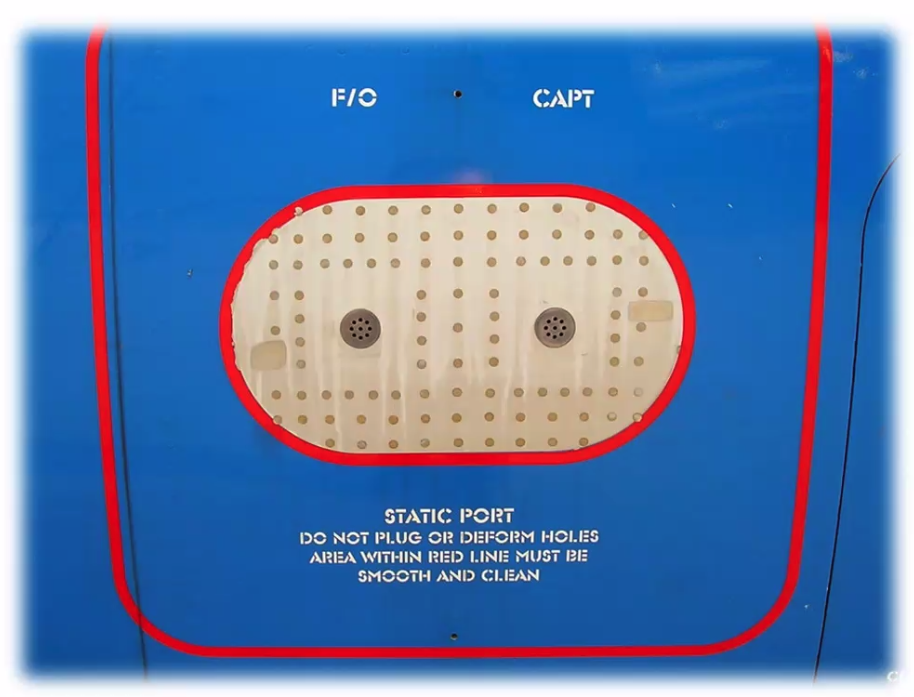
Static Port
- One on early Cessna types
- Two on most light aircraft
- Errors cancel each other out
- Multiple on large aircraft
- May be heated
- No dents/chips within that line
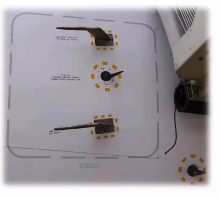
Multiple Sensors
- Two pitot / static sensors
- AoA vane
- Temp probe
- free of dent / chips
Alternate Static Source - Light Aircraft
- Suspected static port blockage
- Pull to admit cockpit air - airflow is slightly lower pressure, over reads slightly
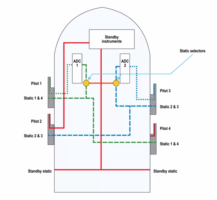
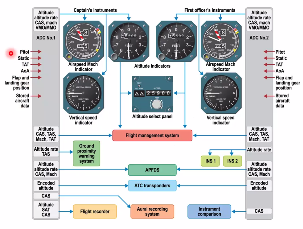
Basics of an ADC, Large aircraft will have multiple ports and duplication for redundancy
Large AC Schematics
- Duplication for redundancy
- cross fed to cancel out errors
- interchangeable parts
- not all ports used on all stations
- standby fed directily - bypassing ADC
- no alternate static - pressurised
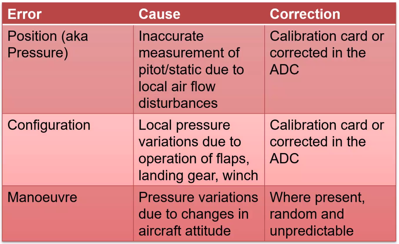
Pitot Static System Sensing Errors
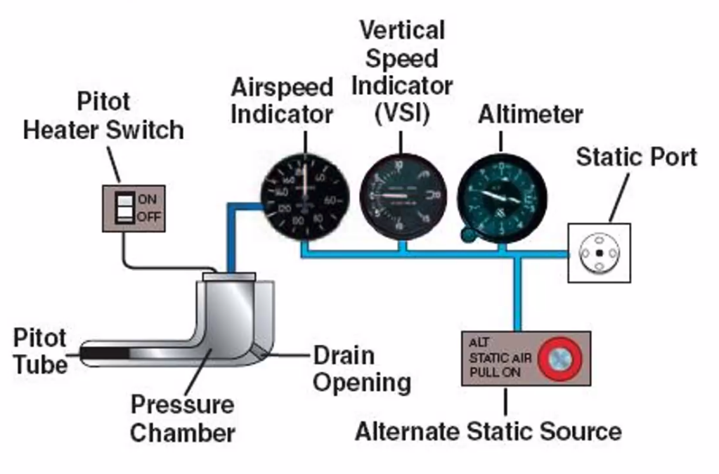
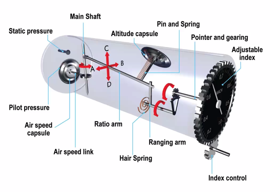
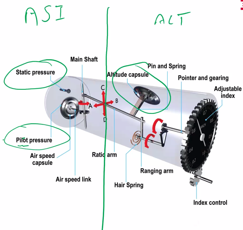
Simple Altimeter
- Aneroid Capsule
- Static pressure fed
- Partially evacuated capsule
- Reacts to pressure changes
- Subscale control to set QFE/QNH
- Basically a barometer calibated to height
Blockages and leaks
- Static port blocked - indication freezes, use alternate static source if possible, which will over read (a bit)
Errors
- P - Position Error / Pressure Error
- I - Instrument
- T - Temperature
- H - Hysteresis (degrading of the elasticity/sensitivity over time)
- B - Barometric
- L - Lag
- O - Orographic
- T - Transonic Jump (Supersonic airflow over the wing, to the shock wave. Causes instruments to jump (not in exam))
“High to low, careful go”
Altimeters
Subscale ranges
- UK 800-1050hPa
- US 950 -1050hPa
Pressure Altitude
- Pressure altitude = Flight levels
- standardised Flight Levels with altimeter set to 1013.25hPa set
- True height of a pressure altitude goes up and down with temperature and surface pressure
LO: ‘the pressure altitude is the altitude in a standard atmosphere that corresponds to the actual static pressure’
Density Altitude
- Pressure Altitude corrected for Temperature
- Used for performance calculations
LO: ‘the density altitude is the altitude of the standard atmosphere which has the same air density as the actual conditions’
Sensitive Altimeter
- two aneroid capsules
- dual gearing to reduce friction (and lag)
- has a vibrator to tap the back of the screen to prevent the stiction of the needles
- capsules move a dial via a gearbox
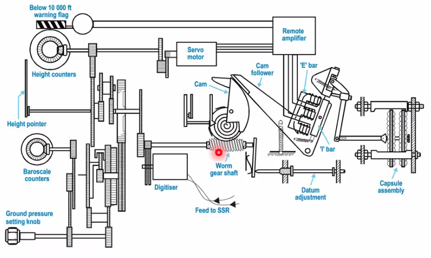
Servo Assisted Altimeter
- two or more capsules for sensitivity
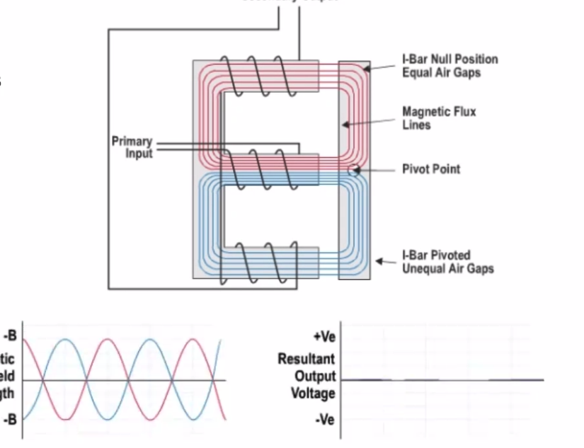
- Moves the I bar against an E bar which will detect / pick up the resistance / flow of the difference of the movement of the air gap between the E/I bar
- Backdriven cam resets the I bar
- Creates a current that drives a servo motor
- motor drives gear to dial face
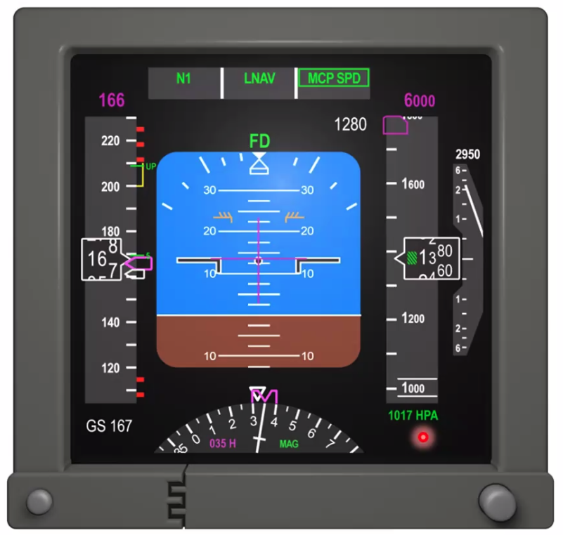
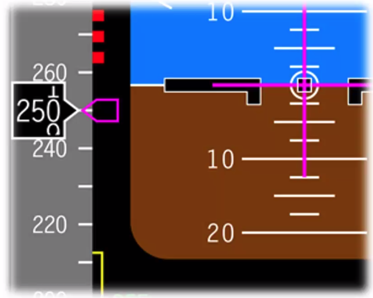
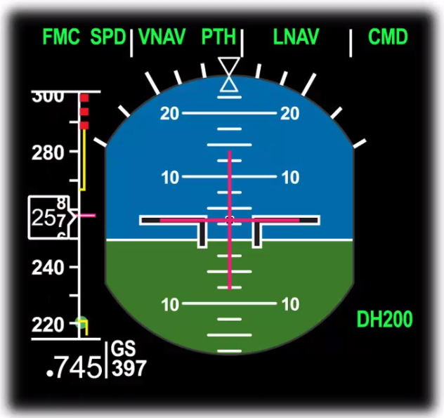
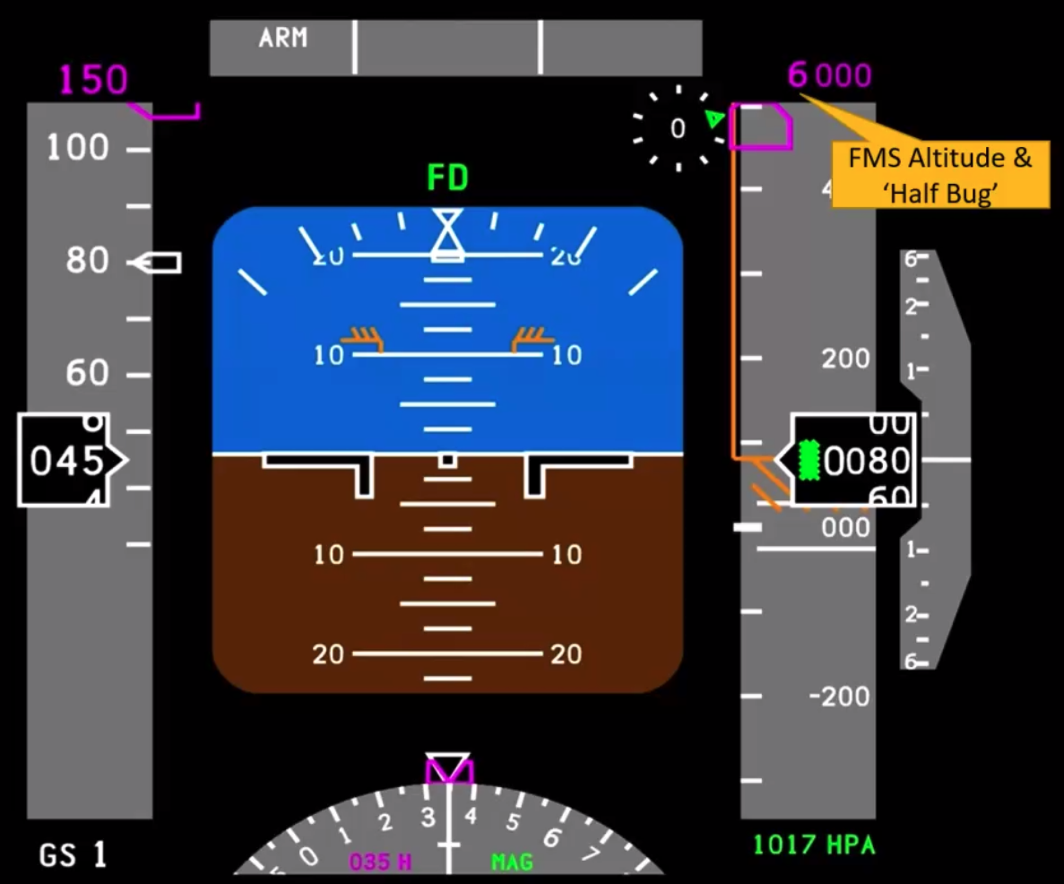
ADC Driven Systems - EFIS
- Accurate indication inside pointer
- Note hatched area on altitude
- Tape translates behind pointer
- FMS selected ALT at top (magenta)
- QNH indication at bottom
- hPa, in/Hg or STD through DCP
Accuracy Limits
- 20m or 60ft for altimeters with a test range of 0 to 9000m (0 to 30000ft) OR
- 25m or 80ft for altimeters with a test range of 0 to 1500m (0 to 50000ft)
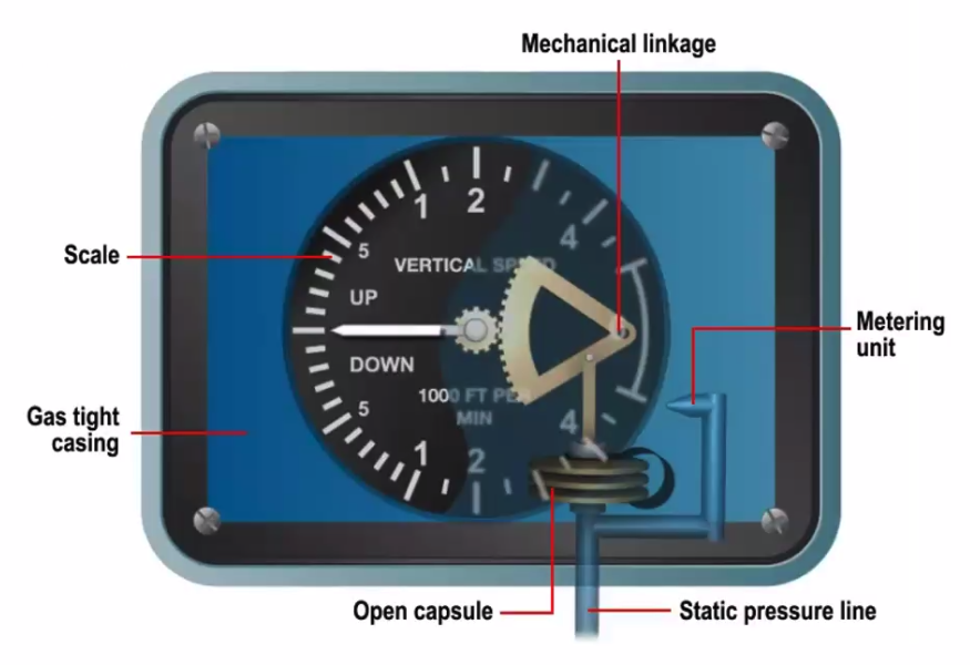
The Simple VSI
- Static air admitted to instrument into
- Open capsule AND
- Metered orifice
- choke valve is there to restrict flow, to allow the measurement of the rate of change
- Errors - think PITHBLOT
- Lag
- Pressure
- Instrument
- Blocked - return to 0.
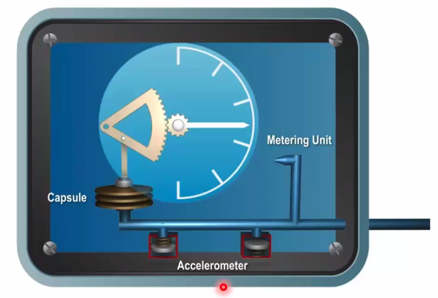
Instantaneous VSI
- Overcomes lag
- ‘Dashpots’ cause immediate differential pressure (aka accelerometers)
- Unreliable when load factor increases - steep turns >40deg AoB
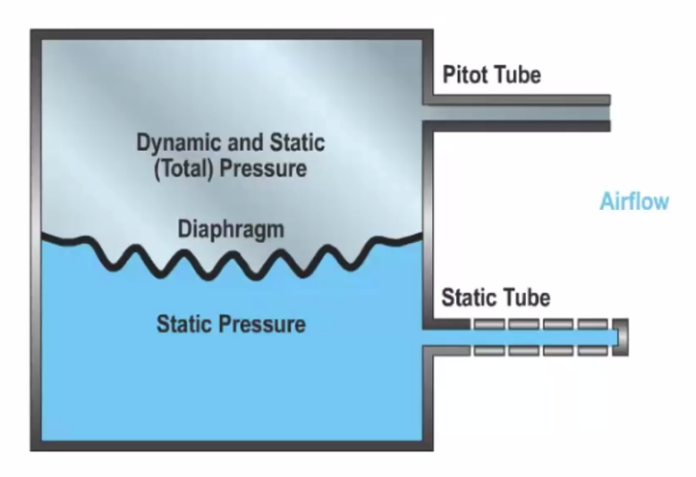
Diaphragm ASI
- Pitot air (dynamic and static) above
- Static air below
- Statics cancel each other out
- Diaphragm movement is dynamic only
- But diaphragm is affected by hysteresis
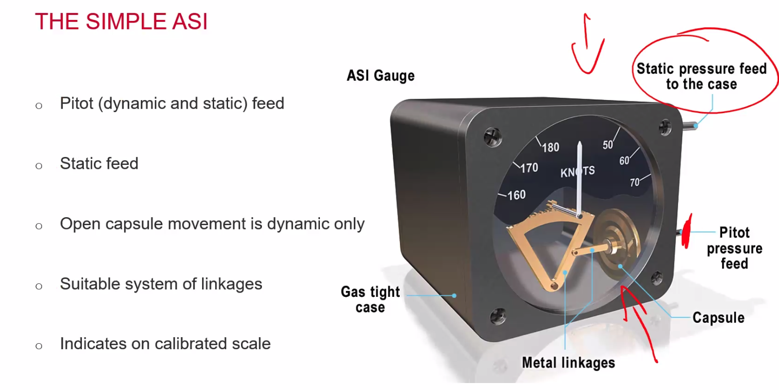
 Simple ASI
 - Pitot (dynamic and static) feed
- Static Feed
- Open capsule movement is dynamic only
- Suitable system of linkages
- indicates on calibrated scale
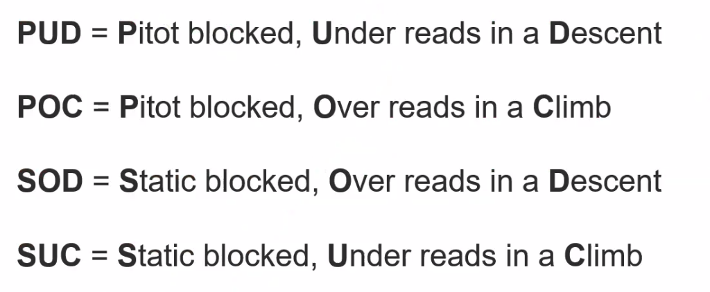
- blocked pitot - PUD, Pitot blocked, underreads in a descent, POC, Pitot overreads in a climb.
- blocked static - SOD, Static OverRead in a descent, SUC, Static blocked, underreads in a climb
Airspeed Indicator
- VSO - Stuff out, stall speed MAUM landing config
- VS1 - Stall speed MAUM, clean
- VMCA - Minimum control speed, One engine Inop.
- VYSE - Best vertical climb, single engine
- VFE - Flaps Extended
- VNO - Normal Operating
- VNE - Never Exceed
- VLO - Max Landing Gear Operating
- VLE - Max landing gear extended
- VREF - Landing Speed
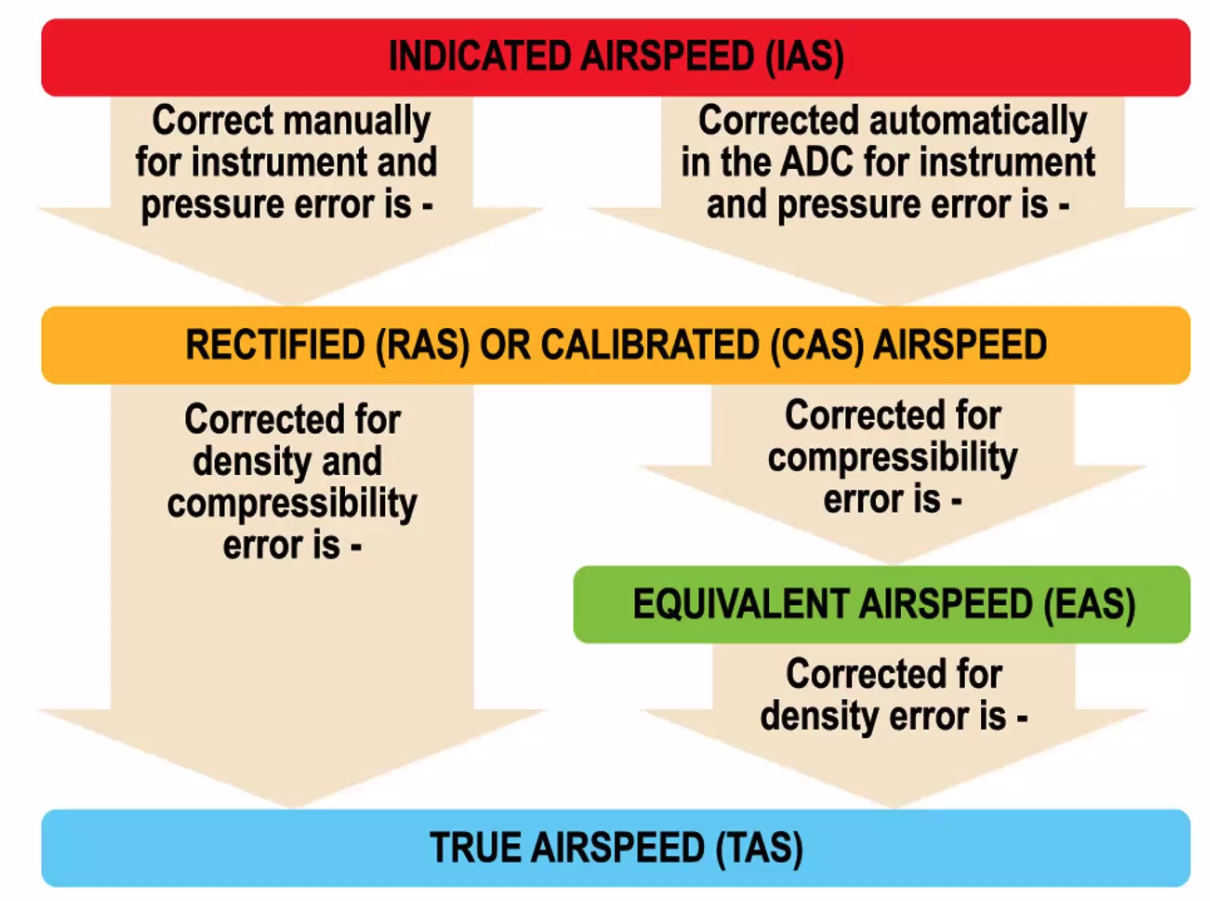
IAS
- whats on the instrument
- subject to uncorrected position and instrument errors
IAS and CAS
- PFD
- IAS corrected for position and instrument errors
- In an ADC CAS is calculated from dynamic pressure using a formula and corrections for position and instrument errors are applied
- CAS is notmally displayed on the EFIS so here, IAS = CAS
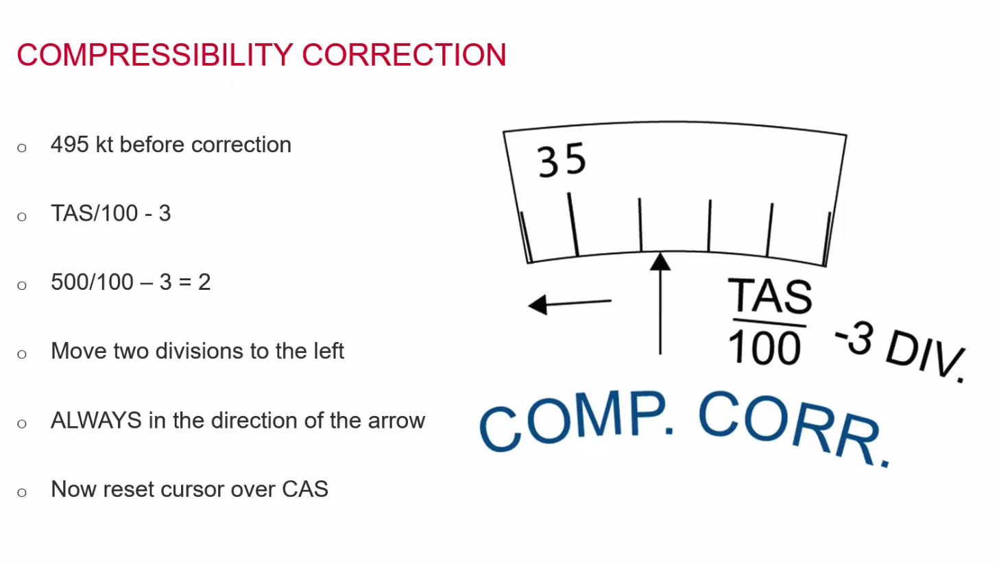
300 knots - anything above and we will correct for compressibility.
CAS and EAS
- CAS corrected for compressibility is EAS
- Compressibility is a function of Mach number, which boils down to CAS and Pressure Altitude
- So Car and Pressure altitiude derives EAS, or EAS and pressure altitude derives CAS
- Compressibility is negligble below 300kt
- At low speeds CAS = EAS
- Compressibility correction is always negative so, as mach number increases CAS greater than or equal to EAS
EAS and TAS
- EAS is the speed at ISA sea level where the dynamic pressure is the same as the TAS as altitude
- So at ISA sea level EAS = TAS
- The correction between EAS and TAS is for density or density altitude
==Q. FL400, OAT -56.5C, CAS 250kt, Determine the TAS== A. 475kts
==Q. FL250, OAT + 10C, CAS250kt, Determine the TAS== A. 395kts
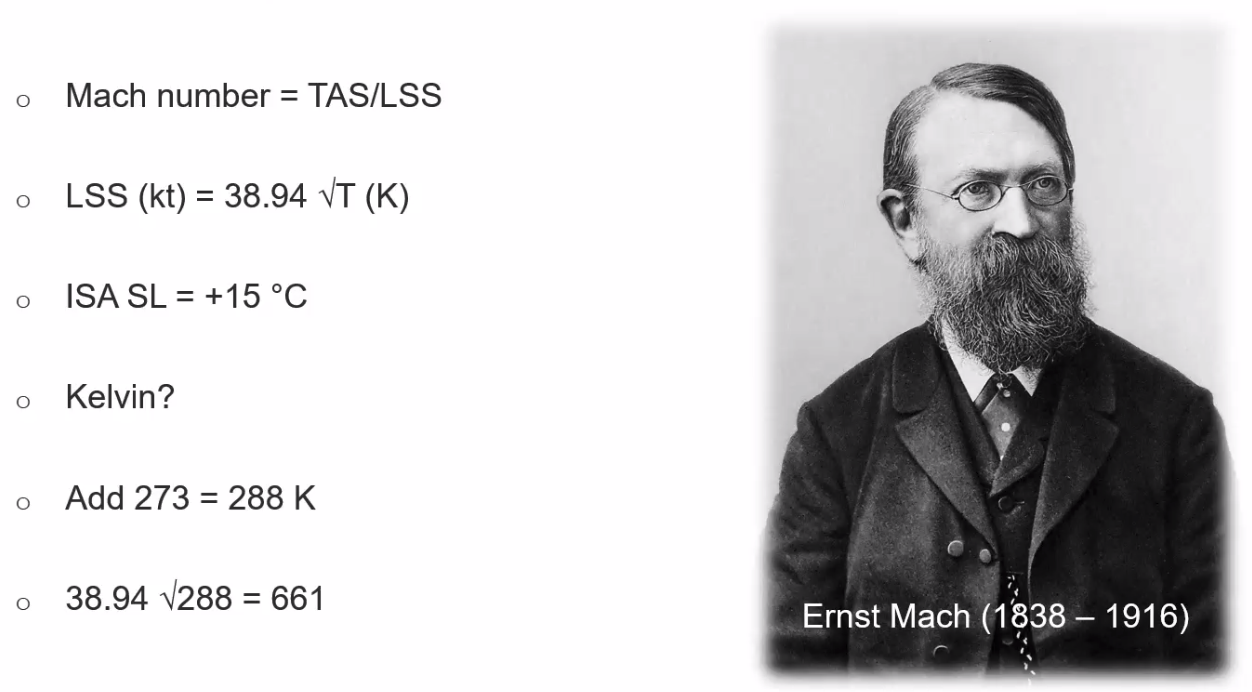
The Machmeter
- Doesn’t need temperature because we’re comparing TAS (temp dependant) with K (temp dependant too)
- Pressure instrument
- No temp input
- Altitude capsule compensates
- M = Pt - Ps/PS
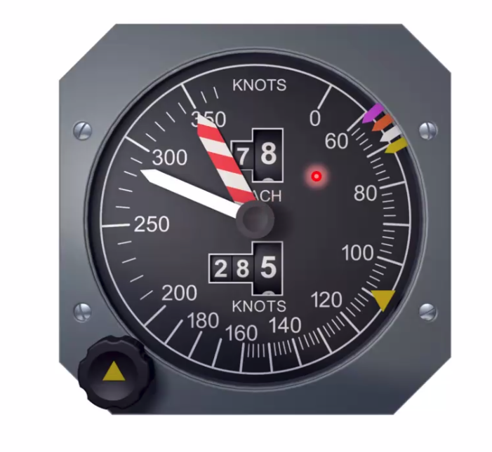
ADC Driven IAS / Machmeter
- VMO/MMO indicator in CAS
- Moveable/ selectable bugs
- Striped barber pole
 EFIS MACH INDICATIONS
- calculated by the ADC
- Digitally displayed
- normally near the CAS
- All speed indications grouped together
MACH Calculation
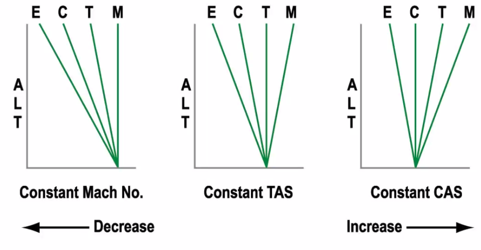
Q. During a climb at a constant CAS, below the tropopause, what happens to TAS and Mach number? A. Tas and Mach both increase
Q. During a descent at a constant CAS through an isothermal layer what happens to the TAS and Mach? A. Both Decrease
If in an Isotherm, the T and M will be the same because its a layer of constant temp.
Q. Flying level at a constant CAS if the temperature increases what happens to the TAS and Mac Number? A. TAS Increases
Because the air is thinner, aircraft can move though easier, so TAS will increase.
ADC Inputs
- Pitot
- Static
- TAT
- AoA
- Flap and Landing Gear position
- Stored Aircraft Data
Modern systems are called an ADIRU
Gyroscopes
- rigidity in space
- precession at slower speeds
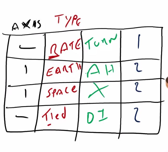
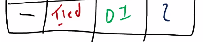
I REST TAXD, Always either 1 degree of freedom, or 2.
- I -
- R- Rate
- E - Earth
- S - Space
- T - Tied
- T - Turn
- A - Attitude / Artificial Horizon
- X - X
- D - D.I
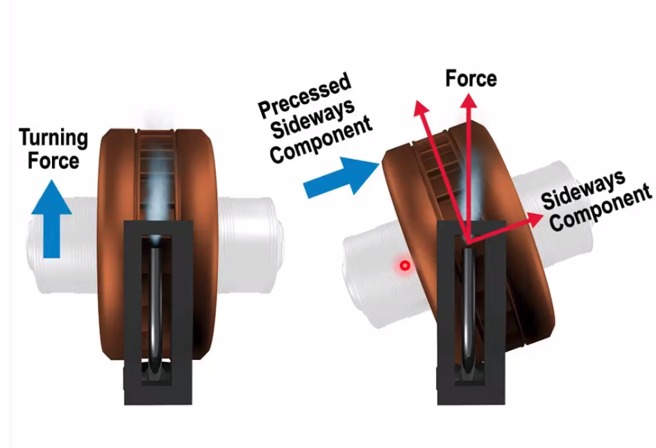
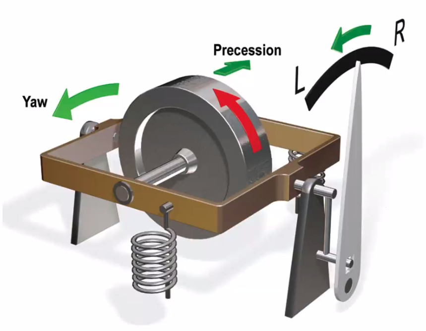
 Precession
- a force applied to a spinning gyroscope acts as if it is applied 90deg in direction of rotation
Rigidity in space
- The spin axis of a gyro remains fixed in space
- rigidity is directly proportional to rate of spin (RPM) & mass of rotor (angular momentum)
- Angular momentum and therefore rigidity are increased by concentrating weight close to the rim
Sources of power
- Pneumatic - air
- simple construction
- cheap(er)
- requires air supplier - restricted freedom
- possible contamination
- Electrical
- constant spin rate
- greater rigidity
- greater freedom of movement
- case can be sealed against contamination
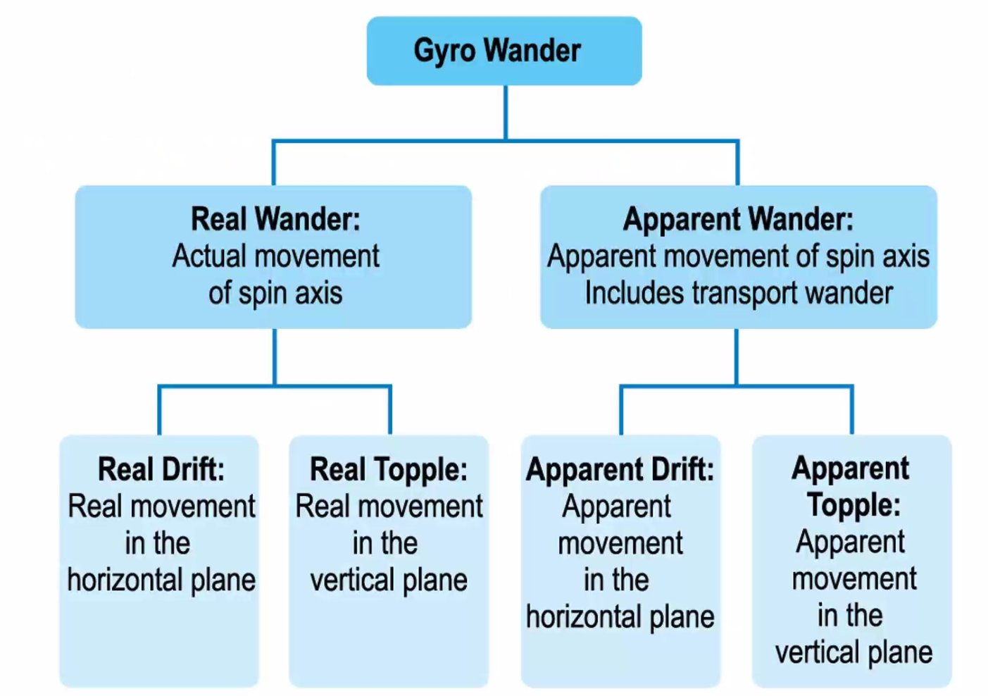
Wander Drift and topple combine to create Wander
- Real wander - from imperfections
- topple - wander in vertical spin axis 15 x cos(lat)
- drift - wander in horizontal spin axis, at its maximum value at the poles. 15 x sin(lat)
- Remember H / V are Earth Terms
- 15 x sin(lat)
Topple
- zero topple at the poles
- maximum topple at the equator
- 15 x cos(lat) - there’s an O in topple, whereas there’s an I in drift.
Transport Wander
- only applied E/W, does not wander N/S
- Is the change of angle between spin axis and true north
- Calculation = Convergency
Apparent Wander
- Earth Rotation
- Zero appart drift at equator
- max drift of 15deg/hour at the poles
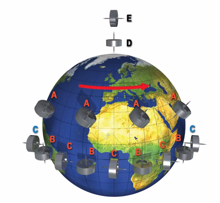
D - No apparent topple E - Maximum apparent drift - 15deg per hour C - Topple - 15deg per hour B - Drift No apparent drift A - apparent drift and topple - drift at 15X sin lat - topple at 15 x cos lat
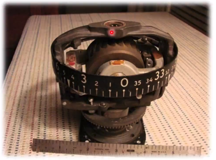
THe direction indicator
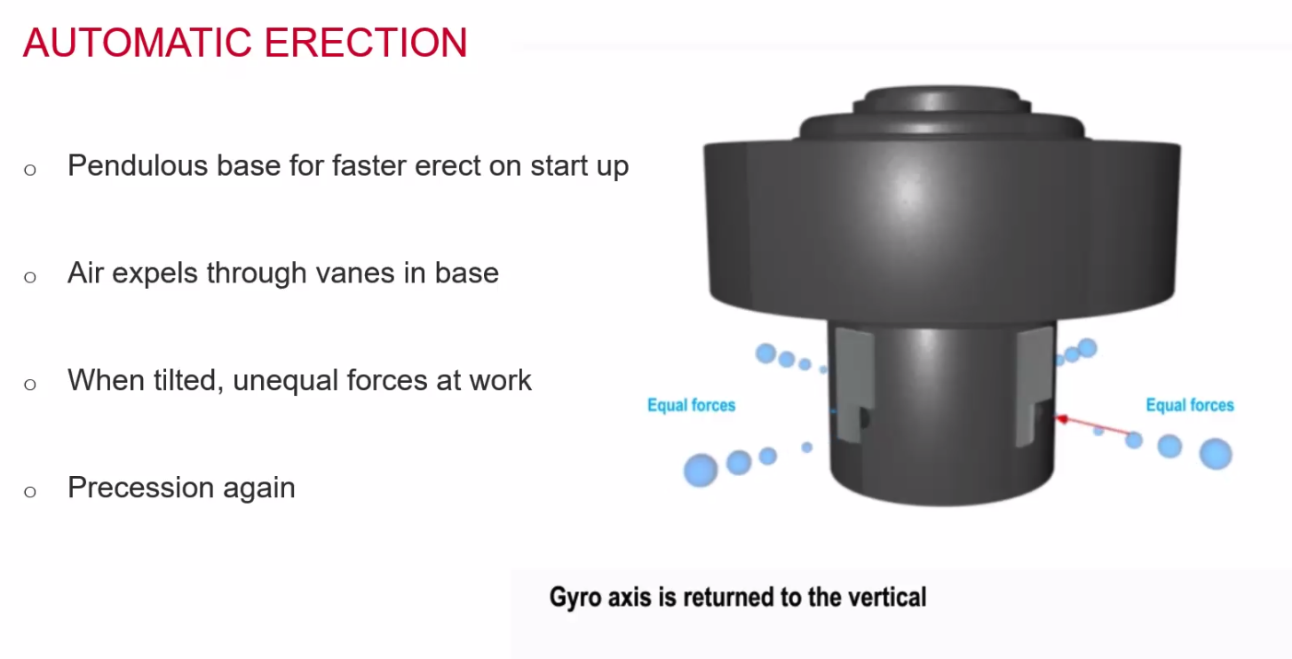
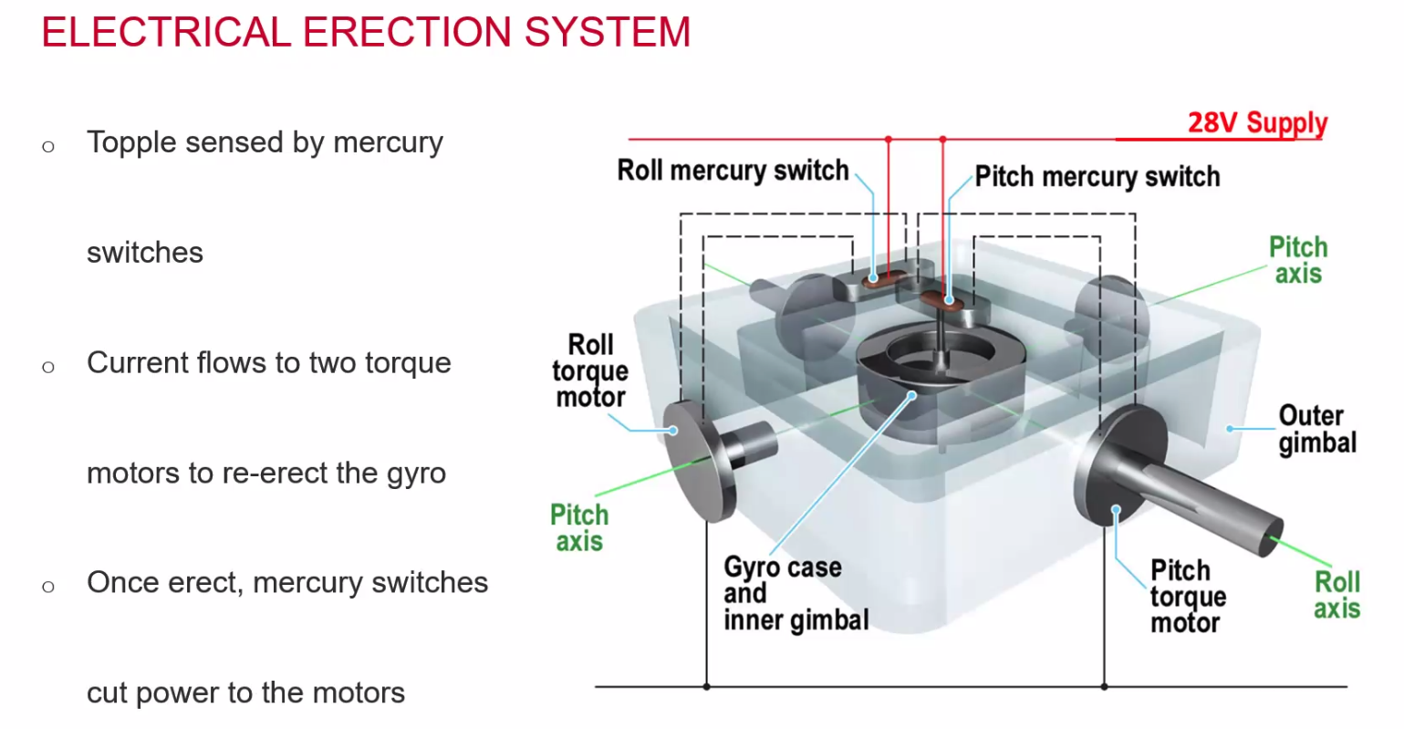
Erection System
- Aircraft banks, tries to take gyro
- we want it to stay in spin axis
- some of the air is sideways
- effect is 90deg later - precession
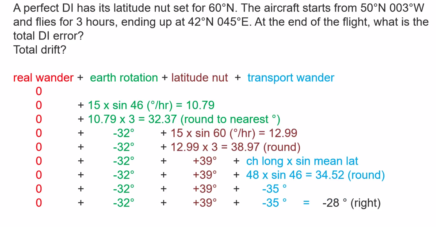
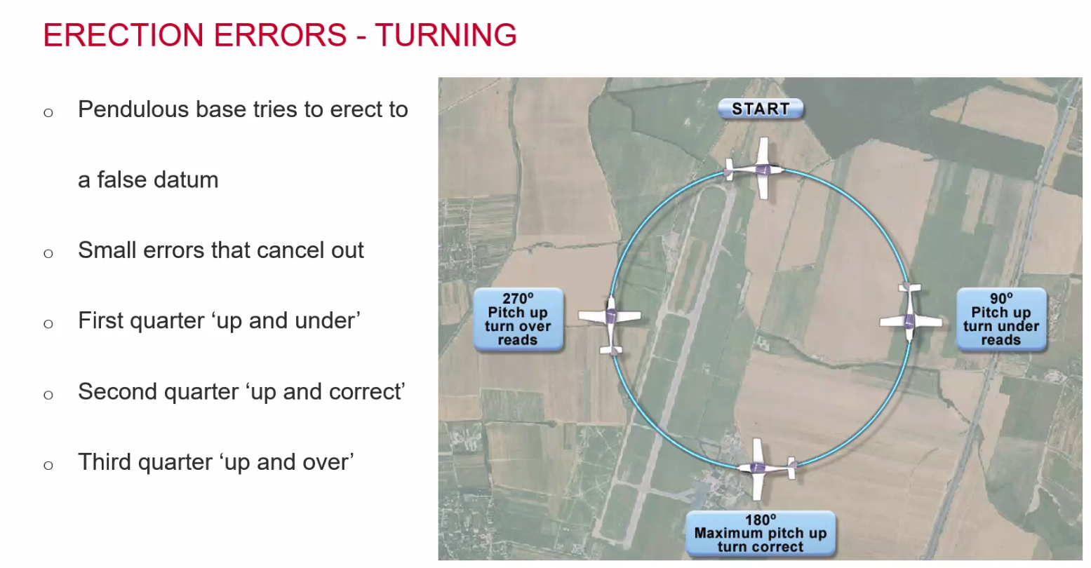
Errors of the DI
- Real Wander
- Gimballing Error
- Earth Rotation
- Transport Wander - compensated by the latitude nut
Latitude Nut:
- The tilt in the gyro matches the tilt of the latitude and gives opposite precession to cancel out the apparent drift.
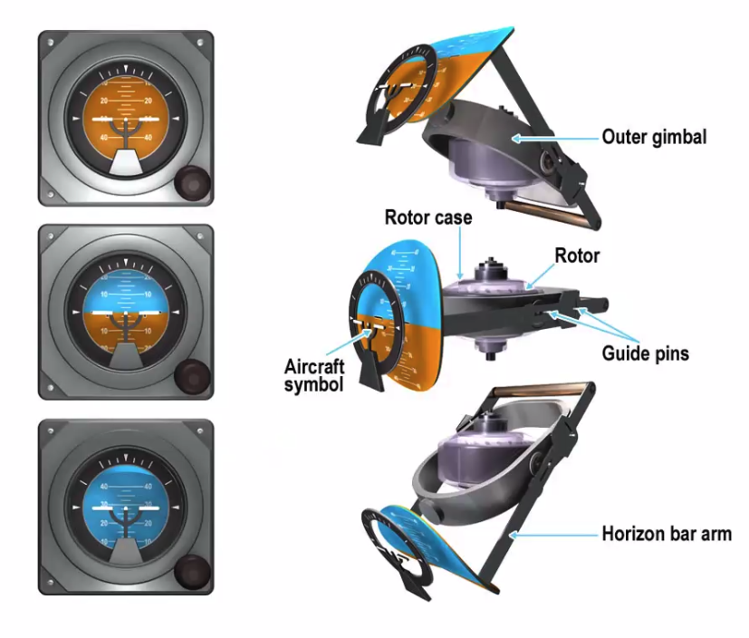
Artificial Horizon
- the vertical reference unit of a three axis data generator
- two degrees of freedom vertical - spin axis gyro
- with its axis earth tied to the local vertical by an automatic erecting system
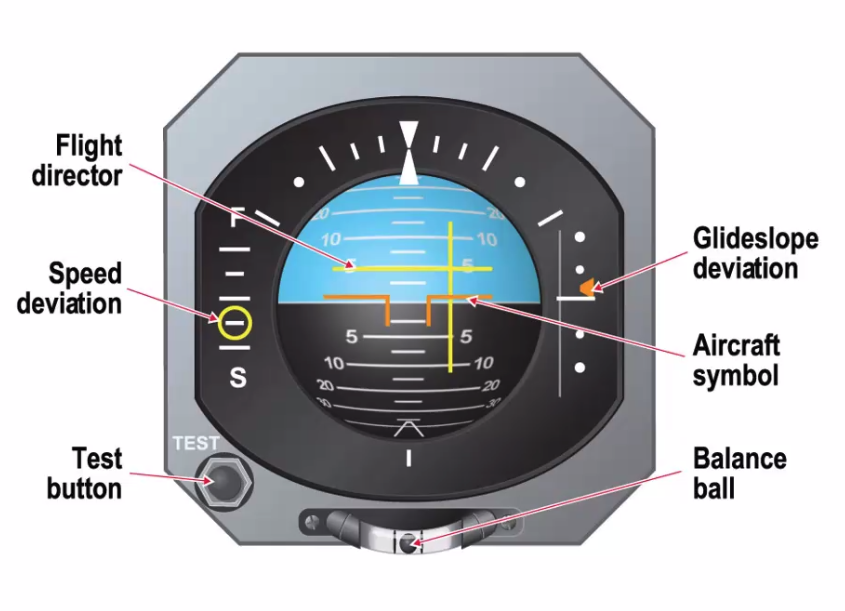
Servo Driven Attitude Indicator
- Driven from remote vertical gyro
- flight director command bars
- ILS glideslope indication
- Speed deviation indicator
- May include Rad Alt info
Turn Indicator
- Measures the rate of change of heading (not the yaw)
- Rate Gyro
- 1 degree of freedom
- Frame is controlled by two springs
- spinning axis is parallel to the pitch axis, which is the lateral axis of the aircraft.
- Errors
- calibration - TAS must be within around 5% of the calibrated value
- Pitch or looping error
- steep turns are more pitch than yaw
- only indicates correctly at its calibrated rate
- typically rate 1 only
Rate 1 turn calculation
- 10% of TAS + 7
==Q. What angle of bank is required for a rate 1 turn at 120kt TAS?== A. 19 degree
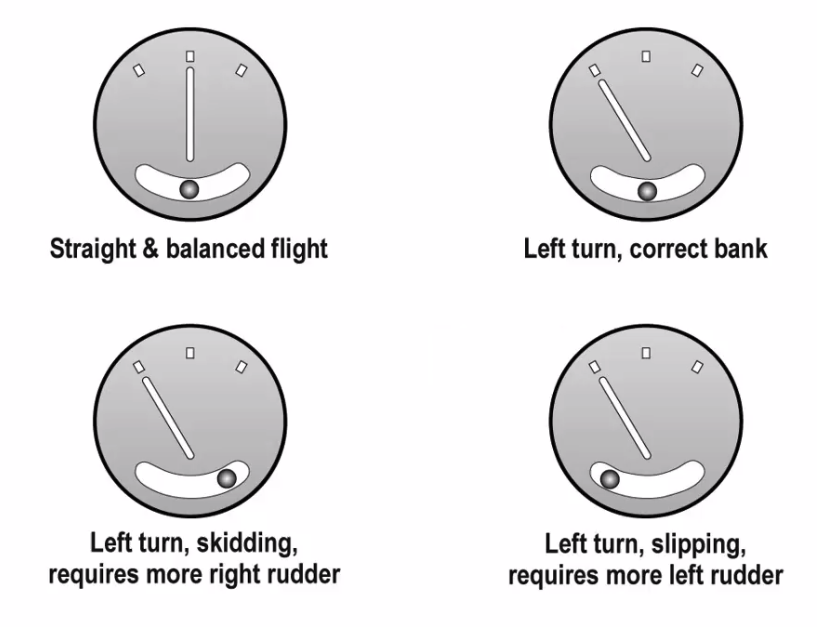
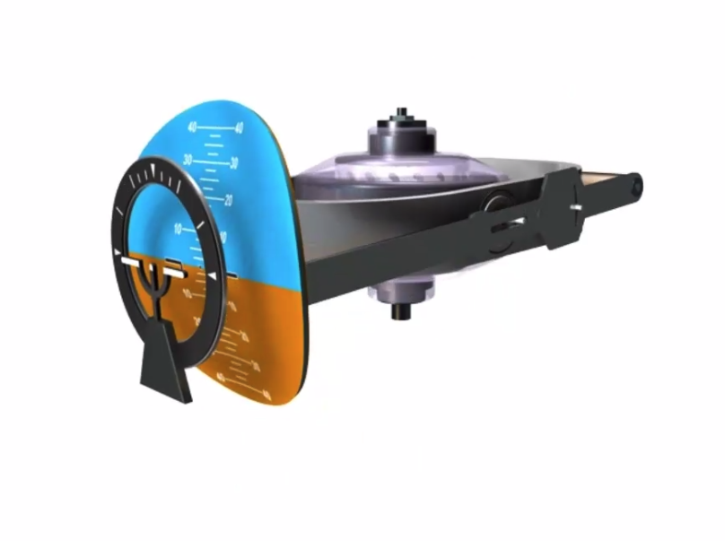
Turn Indicator
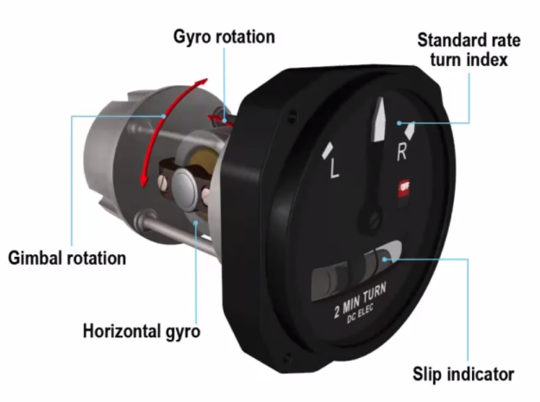
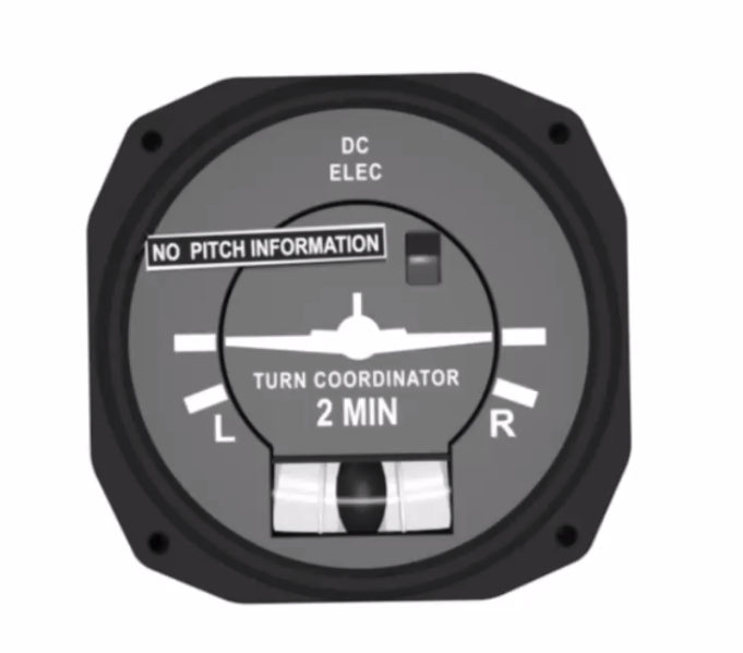
Turn Co-ordinator
- tilts the gyro up by 30deg
- Makes it slightly more instantaneous in its indication
- Always will have ‘no pitch indication’
- electrically powered
- balance ball
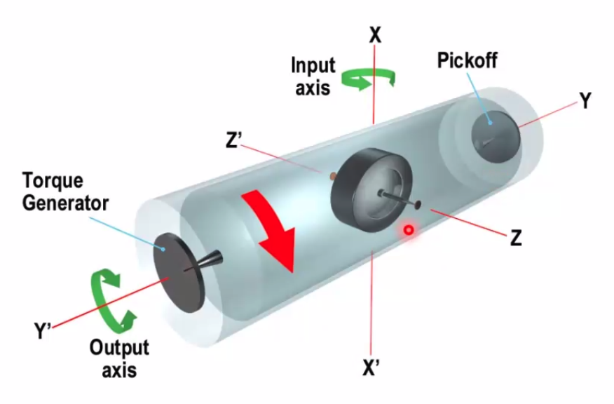
Rate Integrating Gyroscope
- used in Inertial nav system
- Can within a can - the gyro is positioned inside a can which is suspended with liquid inside another can. Allowing the inner can to rotate which can be picked up on the Y axis. Torque motor process bring back to null.
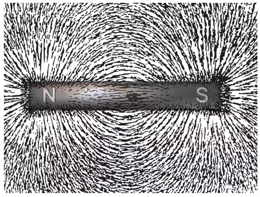
Magnetism
Laws of magnetism
- like poles repel
- unlike poles attract
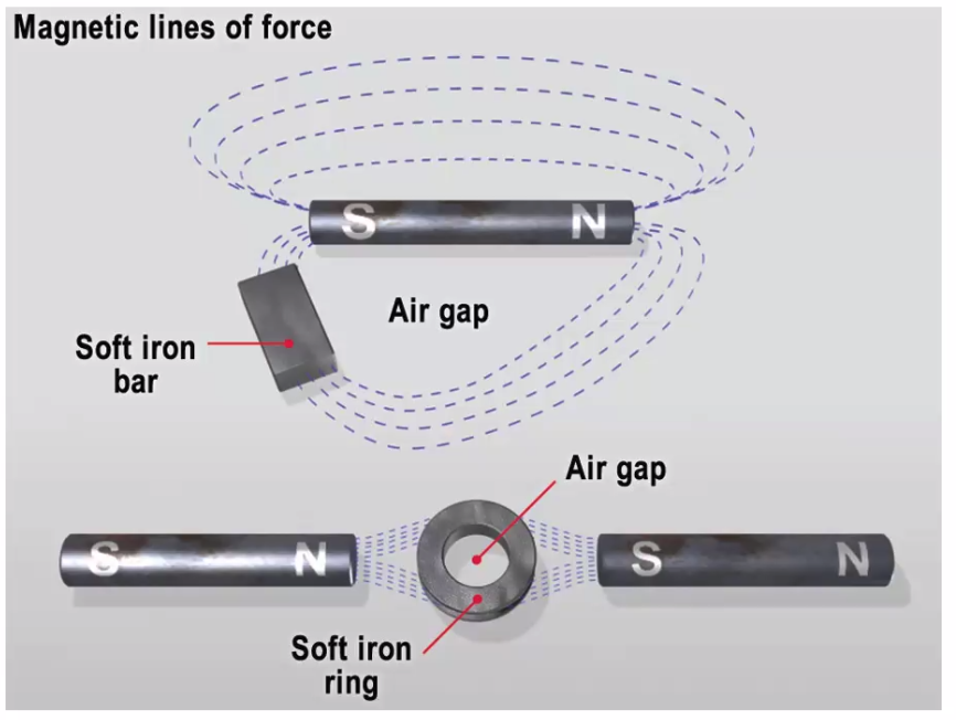
- the poles are not at the exact end of a magnet
- their position is governed by a ratio of magnetic length and width
- short distance in from the end of the magnets
- every magnet is surrounding by a magnetic force
- Unmagnetised - random alignment
- Magnetised by:
- stroking with another magnet
- placing in a magnetic field
- Hammering
- Placing within a DC field
- Soft iron loses magnetism readily
- Hard iron keeps magnetism better.
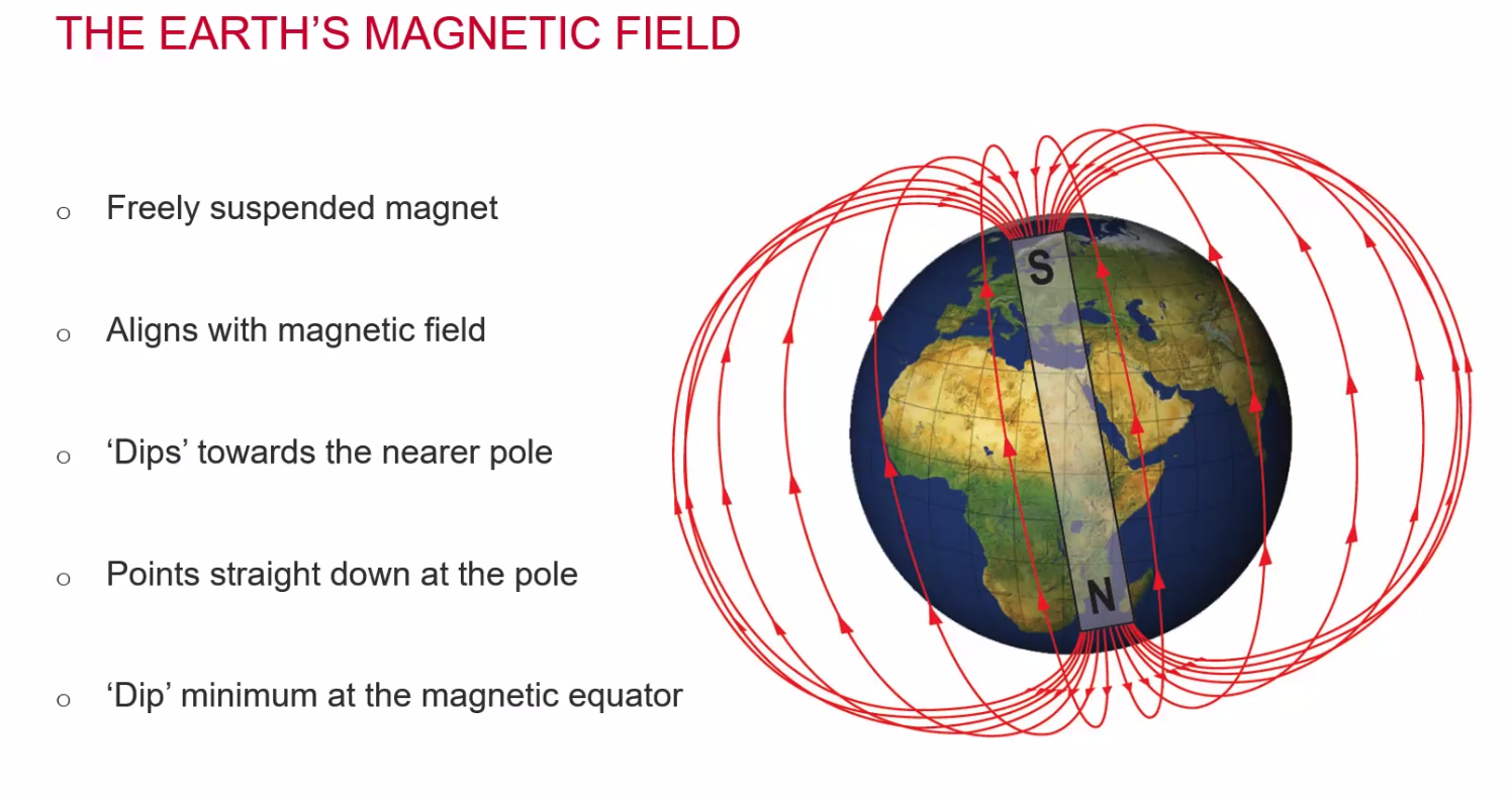
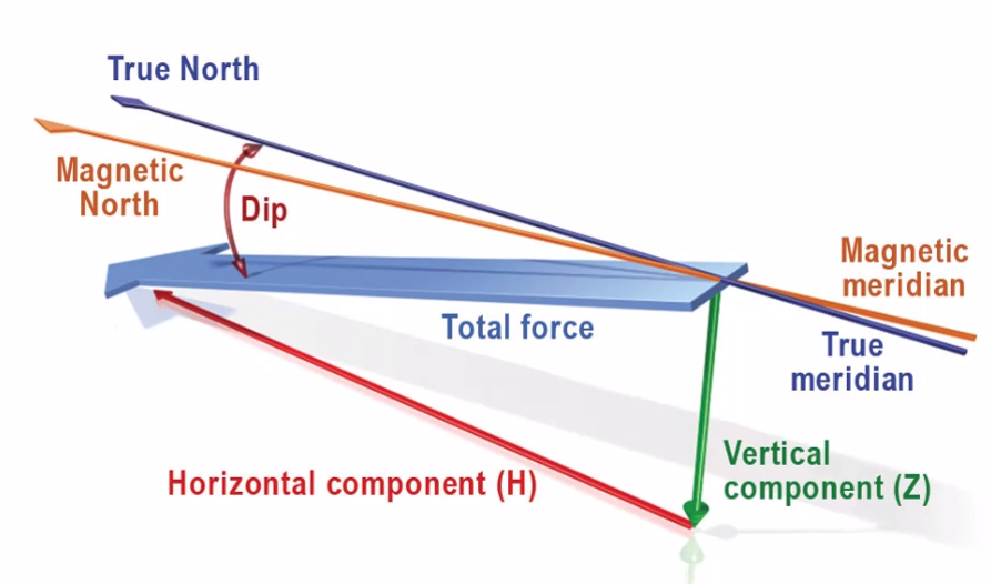
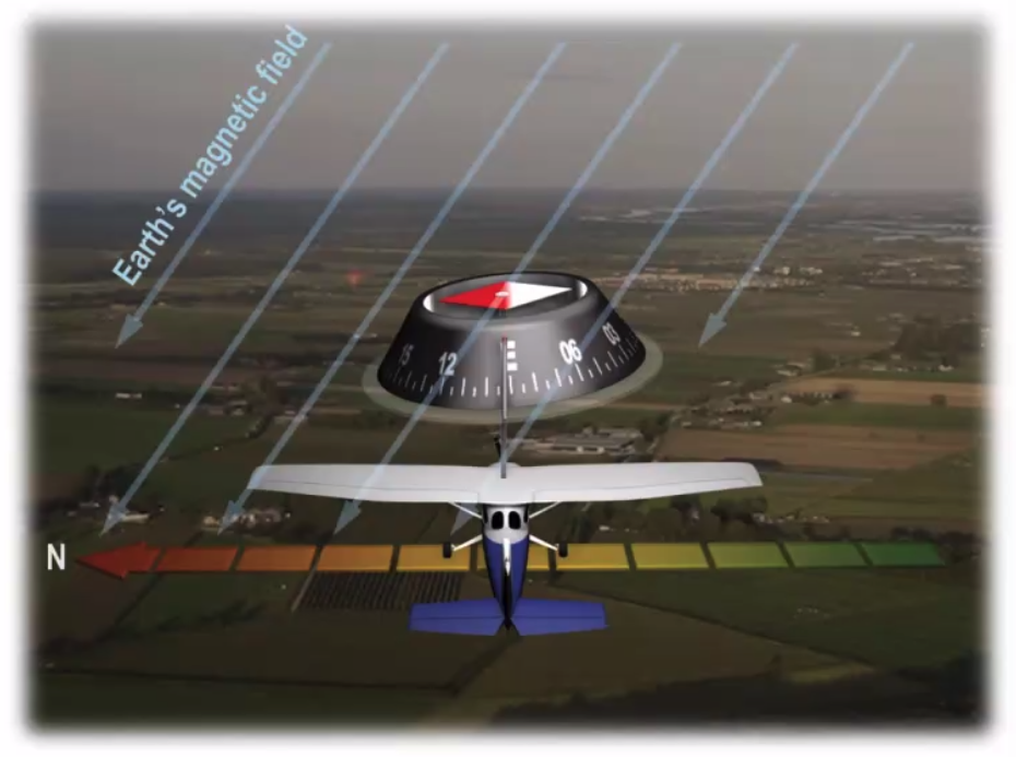
Dip
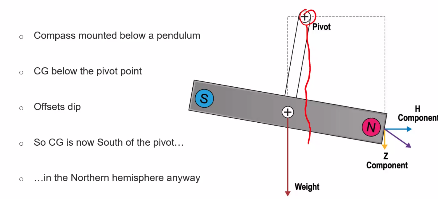
- Remove dip by sticking the magnet on a pivot to allow dip movement
- compass mounted below a pendulum
- CG below the pivot point
Isogonal - line of equal variation Agonic Line - A line of no variation Isocline - A line of Equal magnetic dip Aclinic Line - A line of zero magnetic dip
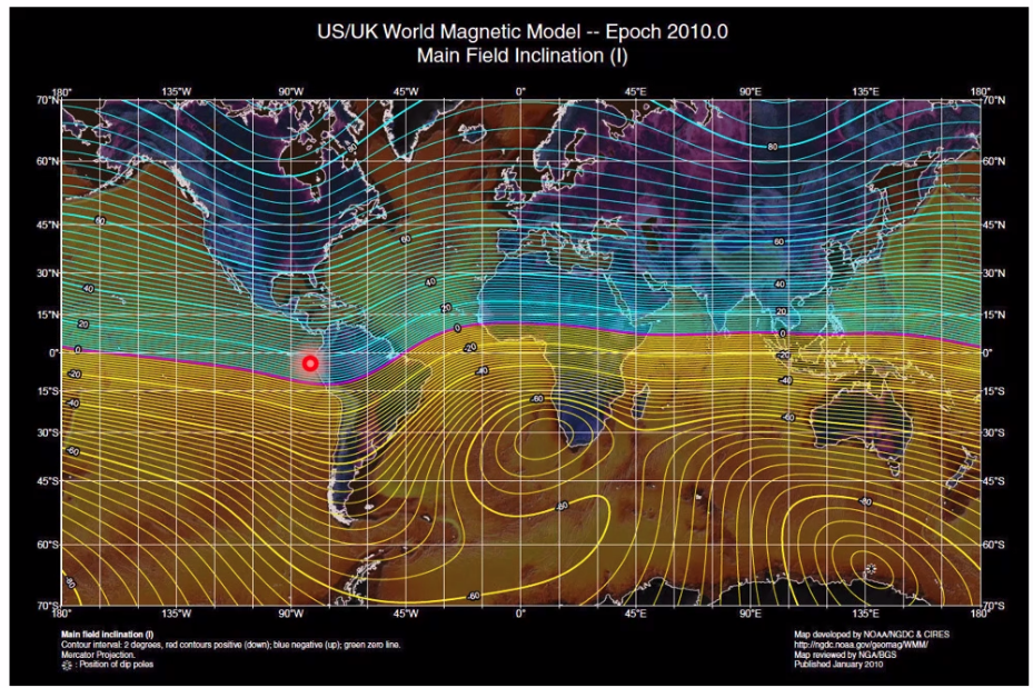
- thick lines going up/down - 20degrees of dip per line
Direct Reading Compass
- Sits in a silicon fluid
- Bellows to account for expansion / contraction
- Pendulous compass card
- Reads back to front
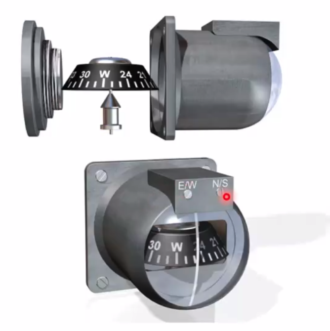
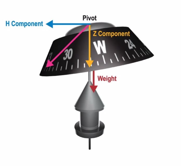
- Pendulum offsets dip, as seen
- CG south of pivot, helps but gives up problems - acceleration errors and turning errors
- ANDS in Northern Hemisphere
- Accelerate North
- Decelerate South
- SAND in South Hemisphere
- South Accelerate
- North Decelerate
Acceleration Error
- Offset CG
Turning Error
- Rolling out on East / West?
- No real effect on compass
- Rolling out North / South?
- Roll out early when turning north
- Roll out late when turning South
- UNOS - Underturn through North, Overshoot through South
- by 20-30 deg.
- Needle tries to follow the field
- Steep Turns
- Field at 90deg to compass, cannot align correctly
- ‘Equal to 180 on a 090 heading in a right turn’
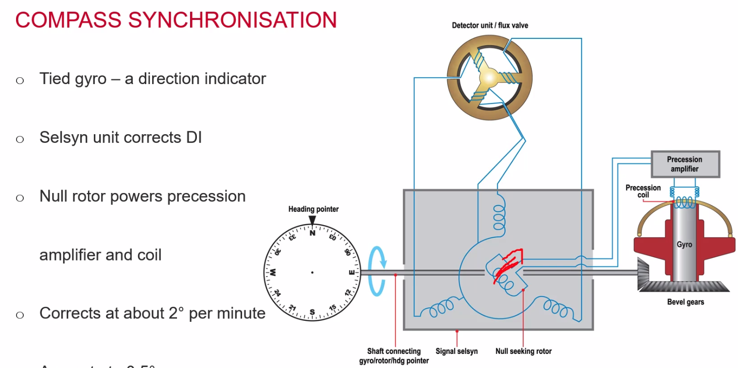
Remote Indicating Compass
- Validates the directional gyro against the compass
- Combines the stability of a gyro with the accuracy of continuous magnetic monitoring
- Comprises of:
- Gyro unit - horizontal, two degrees of freedom,
- Heading indicator
- Flux detector / valve
- Error detector
- Precession amplifier
- Located in a wingtip / away from magnetic items
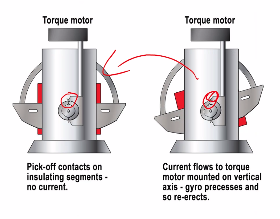
- red highlighted area shows the re-erecting system. The two lines will connect to the bars when rotated to initiate the torque motor to re-align
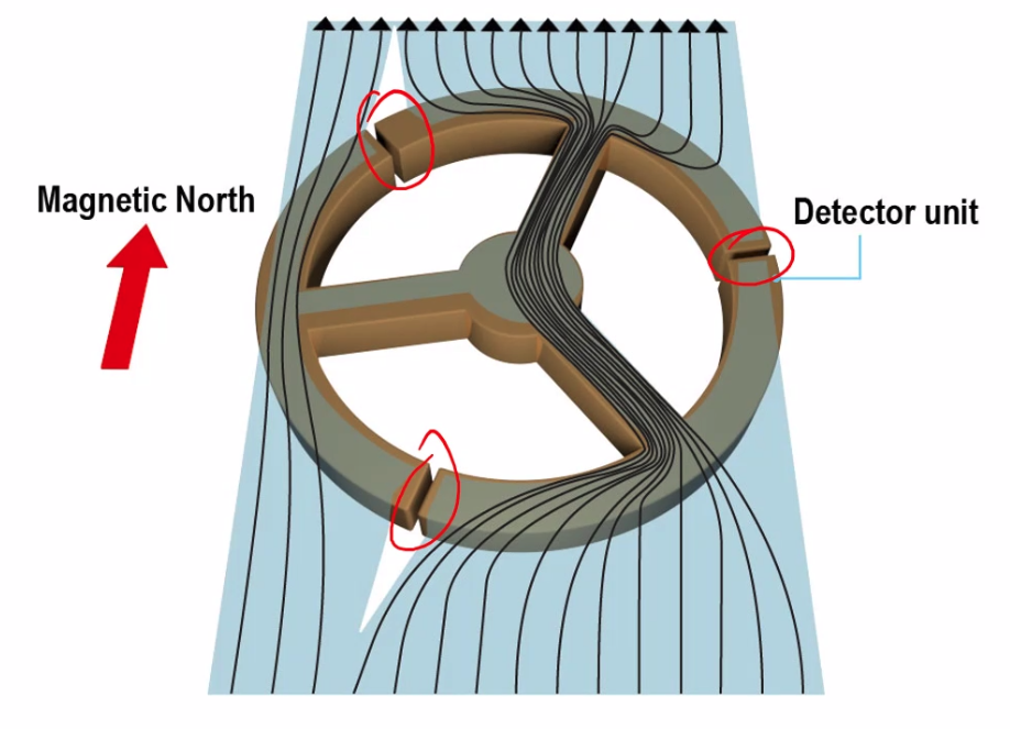
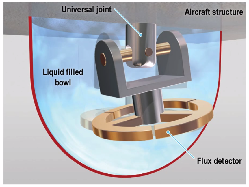
Flux Valve
- detects a change in magnetic force across each magnetic arm.
- three soft iron arms
- magnetic flux flows through them
- air gap dictate path
- damping fluid in the bowl
- suspended in a universal joint
- 25deg freedom in pitch and roll, none in yaw!
- Can pivot up but is fixed to the aircraft azimuth
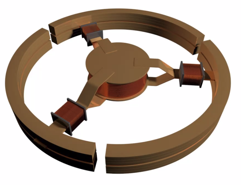
- primary and secondary windings around the
- 487.5 Hz AC in excitation coil
- AC fluctuations picked up in secondary coil, which will not include a steady earth field
- Subtract 487.5 from this to determine magnetic heading
- Then fed into an error detector (stators) and 1 rotor, current induced in rotor except at right angles to the field - that null point is north
- ‘Selsyn’ tells us when it is not so, 90deg out? = 90deg. (look at the smaller coil inside on second image).
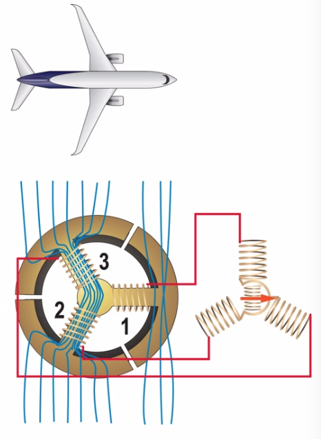
Accurate to half a degree!
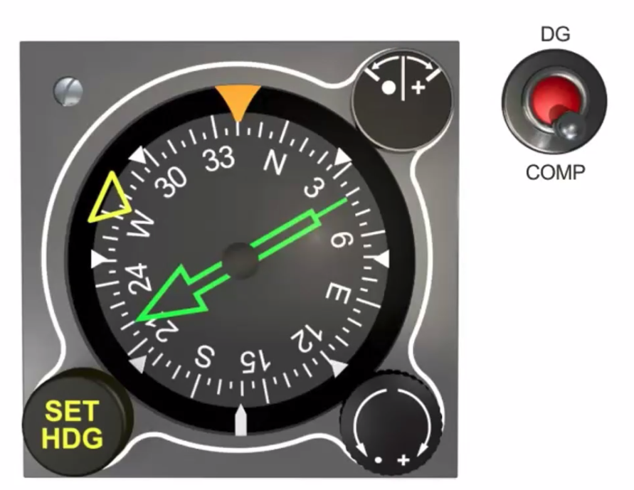
Cockpit indicator
- Annunciator flicks to and fro
- aka ‘dot crossing’
Cockpit Displays
Instrument T
- Selected radial scan, based on master instrument (AI)
- then Airspeed Indicator
- then Alt
- then Compass / Direction / Heading
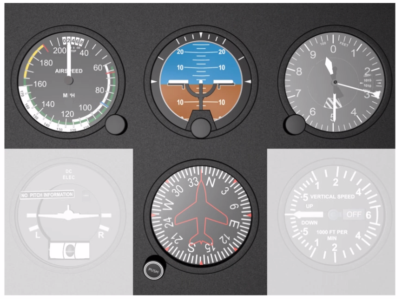
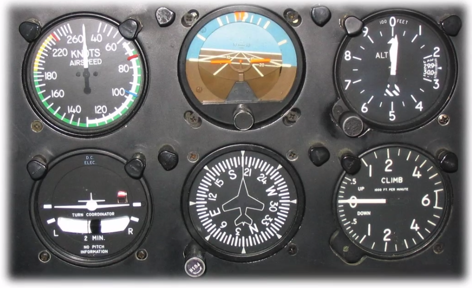
Six Pack
- Six pack analogue
- Duplicated for each pilot (in larger aircraft)
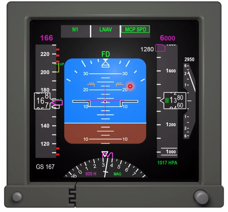
EFIS - PFD / ND
- Same as a six pack but all on one page
- Also includes FMA (Flight Mode Annunciator)
- indicates CAS because its coming from an ADC
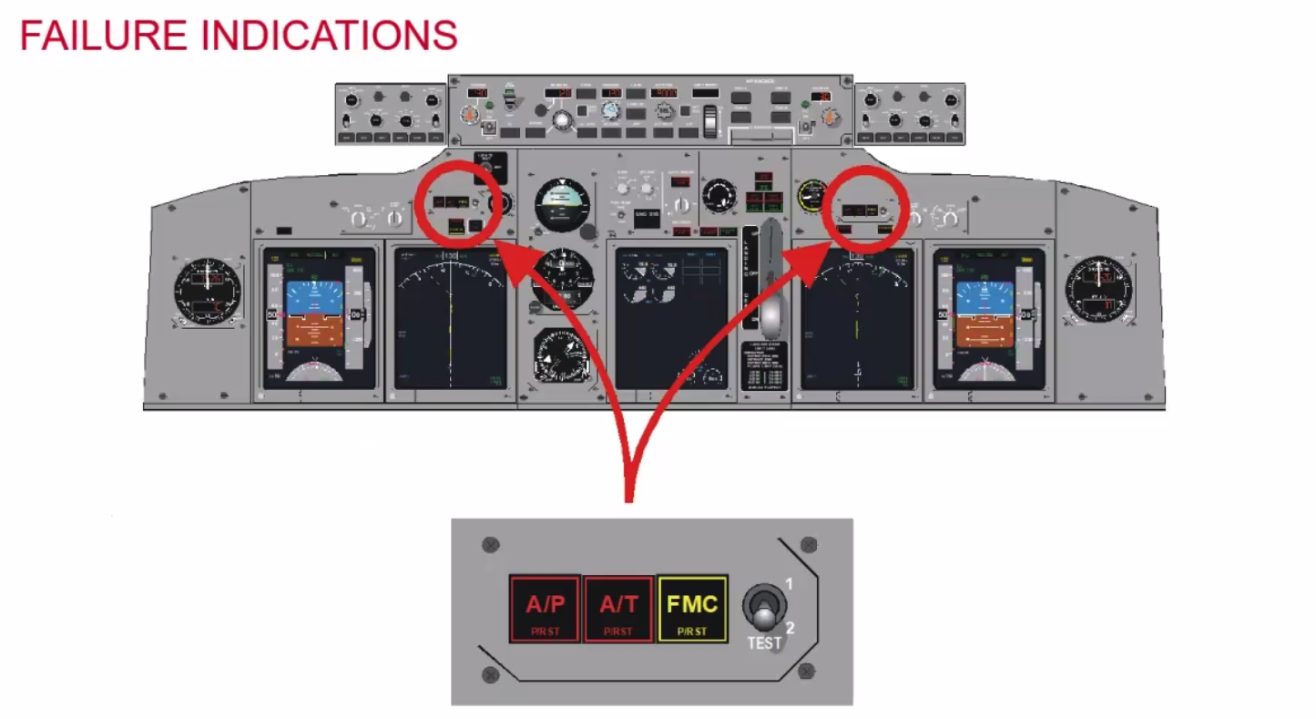
Input Failures:
- Faults generator by a signal generator
- two sides constantly compare data
- Red indications
- Windshear warning
- Pitch or roll greater that 3deg mismtach
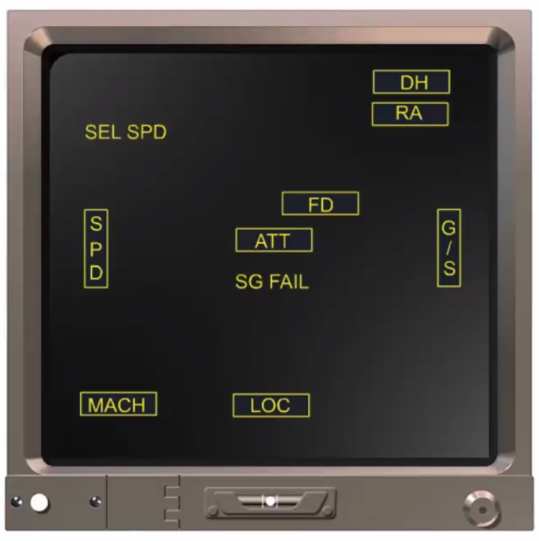
- Orange bar along VSI indicates rad alt
- Green hash within altitude indicator shows under 10,000ft
- Pitch limit eyebrows (just above 10deg) to show pitch limit.
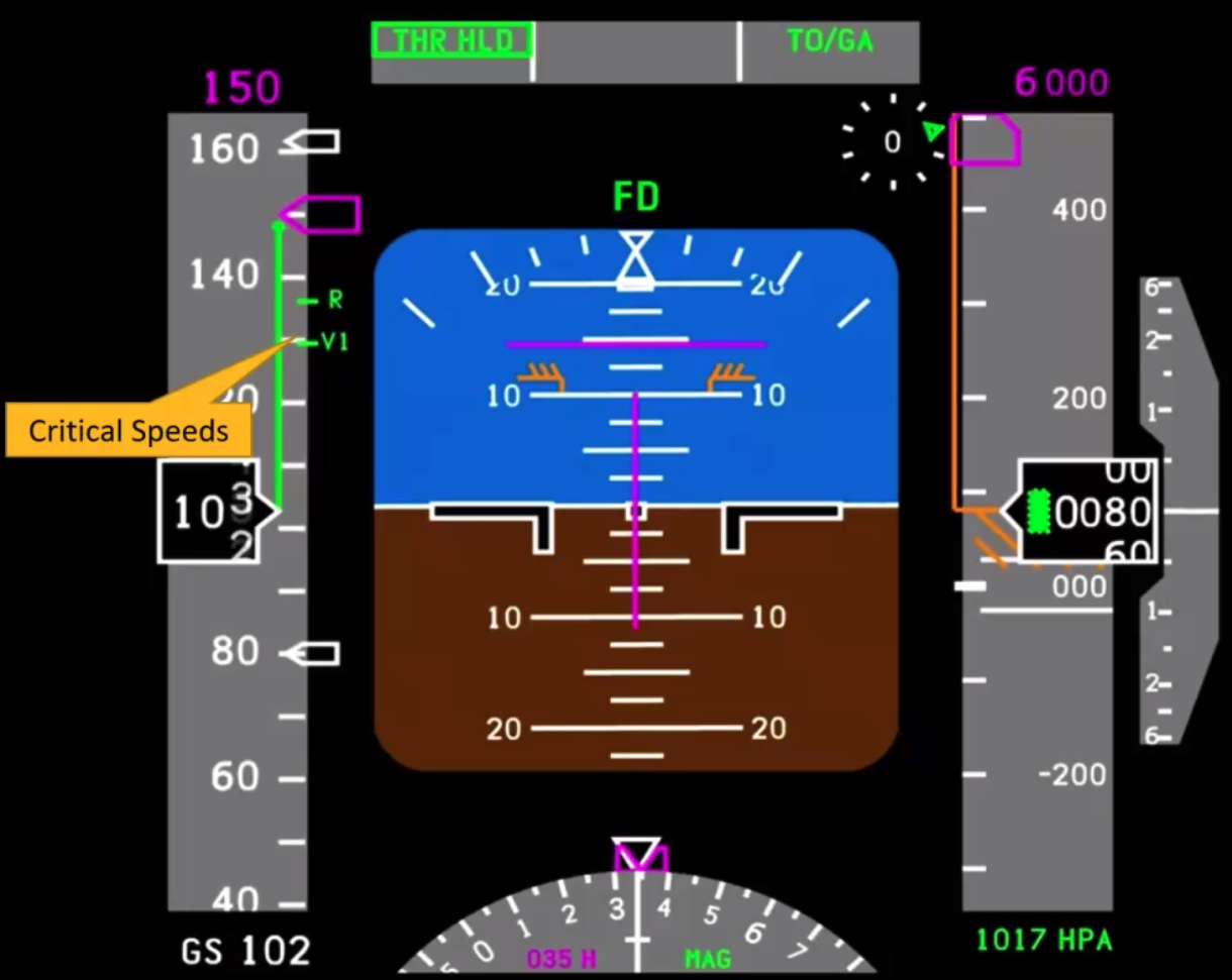
Above image - taking off
- 10 second trend arrow - magenta arrow on the speed tape
- THR HLD - boxed for 10 seconds to indicate recent change, then will look like the TO/GA indication
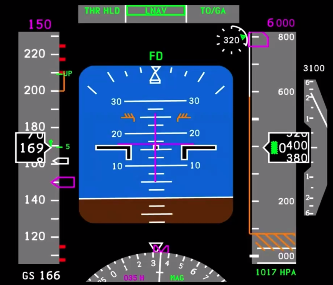 Above image - continuing takeoff
- Flaps up indication along speed bar (green UP)
- Rad alt is alive, filling the arc on the outside, above 1000ft it will go digital until disappearing at 2500ft.
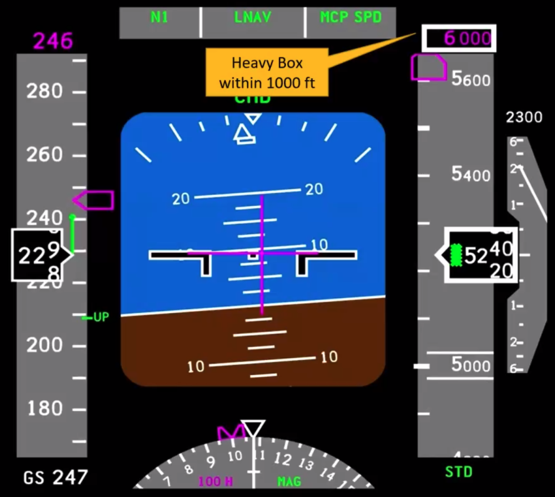 Above image - autopilot engaged
- Heavy boxes indicates within target altitude
- Notice turn co-ord not in balance
- CMD (under the heavy box within 1000ft) - signifies this PFD is command.
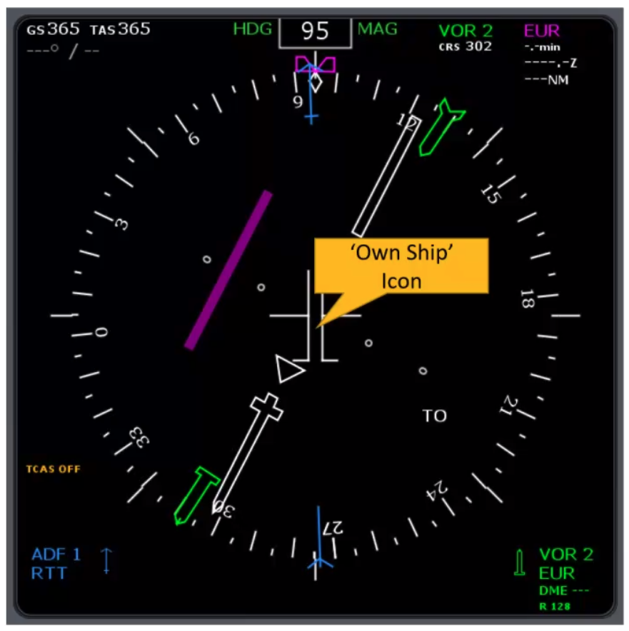
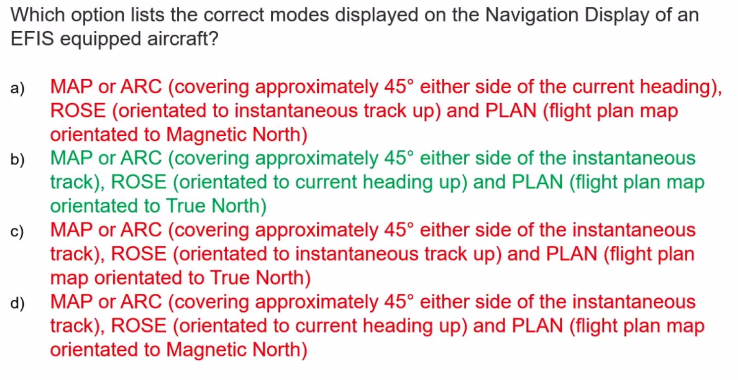
Navigation Displays
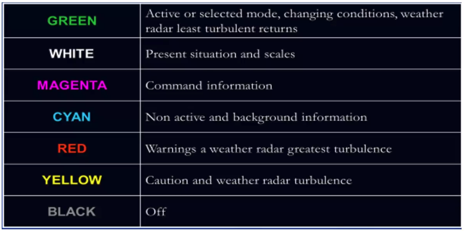
- same colour conventions
- selectable display styles/modes
- variable range rings
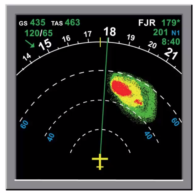
- can include WXR or TAWS - but never on the same screen.
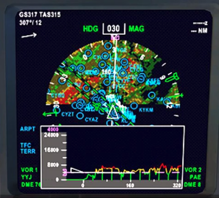
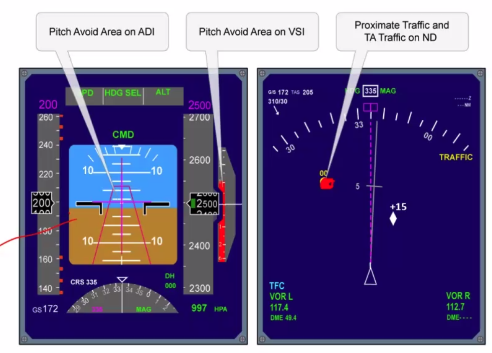
Above image - Full Rose
- ground speed / tas top left
- TCAS off / bottom left in orange
- Nav aid 1 - blue text bottom left and indications on the compass rose
- Nav aid 2 - green VOR text on bottom right and on display
- Waypoint and nav information magenta top right and deviation indicator magenta bar middle diagram
- Track indicator - top of rose in blue, accounts for drift
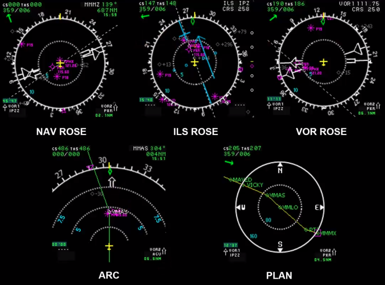
Arc - track view, Rose - heading up, Plan - nav
Some may also have a Vertical Situation Indicator using the lower half of the nav display, includes terrain profile and can show whole or part of flight
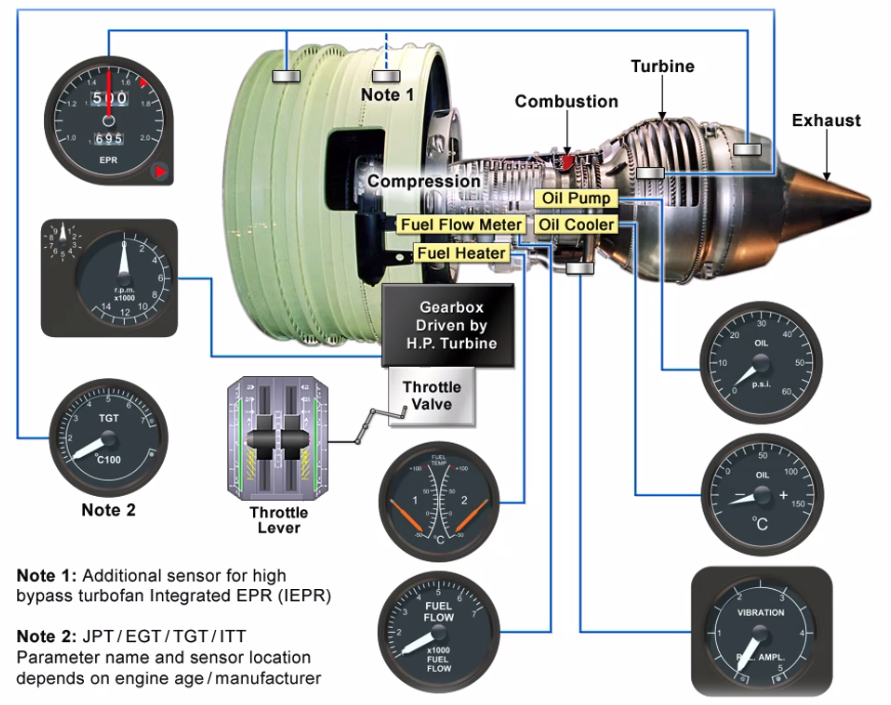
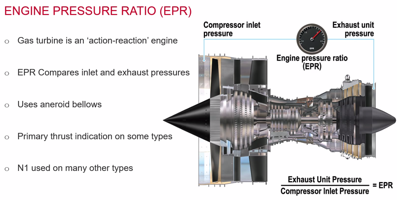
Power Plant Monitoring
- Engine Pressure Ratio
- RPM
- Temperatures
- Pressures
- Fuel Flow
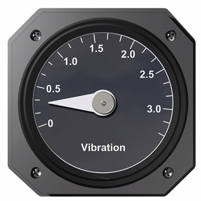
- Vibration
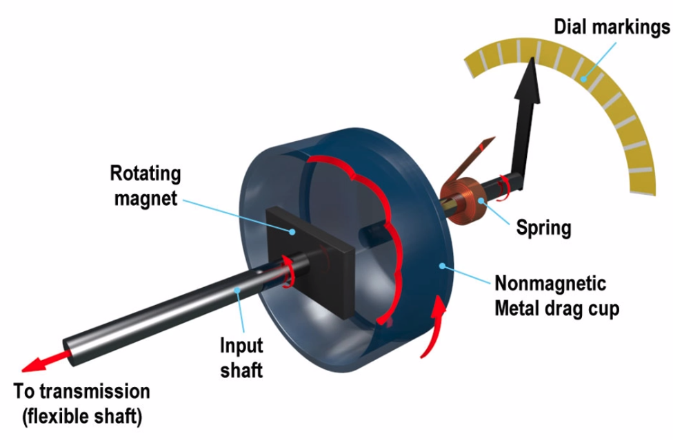
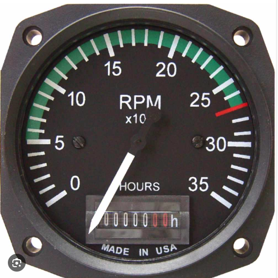
Mechanical Tachometers
- Flexible shaft from the engine
- turns a magnet in a cup eddy current ‘grabs’ aluminium cup, turns against a hair spring
- limited by path length of 2m
- best in straight line - friction
- simple and cheap
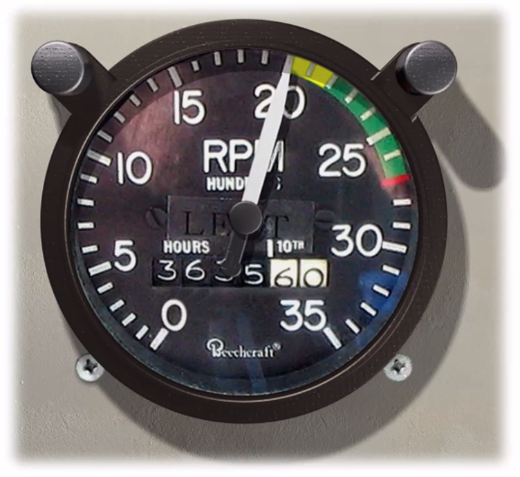 Above image - Mechanical Tachometer
- Yellow - cautionary limit (vibration)
- Green - normal operating range
- Red - maximum limit
- Can include hobbs time indication
- not time based on cruise RPM.
DC Tachometers
- Same working principle as a dynamo light on a bike (magnet turning to produce electricity to create electricity to light a bike light)
- Component measured drives tacho
- tacho generated to instrument by wire
- gauge is a voltmeter
- calibrated in RPM
- Voltage drops
- Problems in exam:
- Line resistance
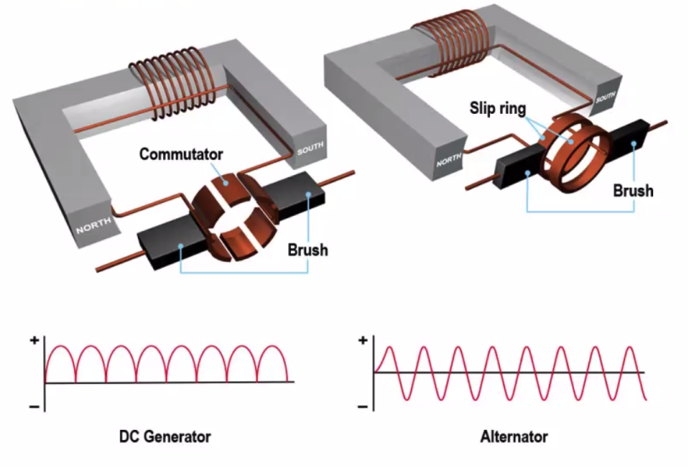
- The way in which we make DC
 Above image - DC Gen
- Lots of Coils
- Multiple cutouts on commutator
- Advantages:
- Simple
- Cheap
- No electrical supply needed
- Disadvantages
- Sparking / Arcing
- Heat/Localised burning
- Interference on radios
- Some sparking / generates static electricity which generates an electromagnetic force which interferes with instruments
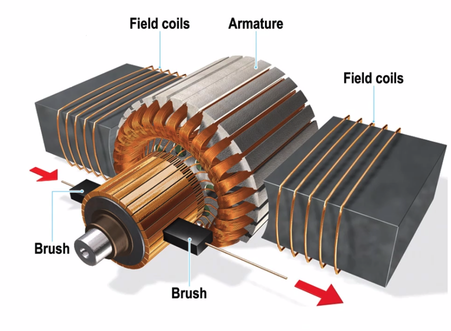
Electrical Tachometer
- does NOT spark / arc
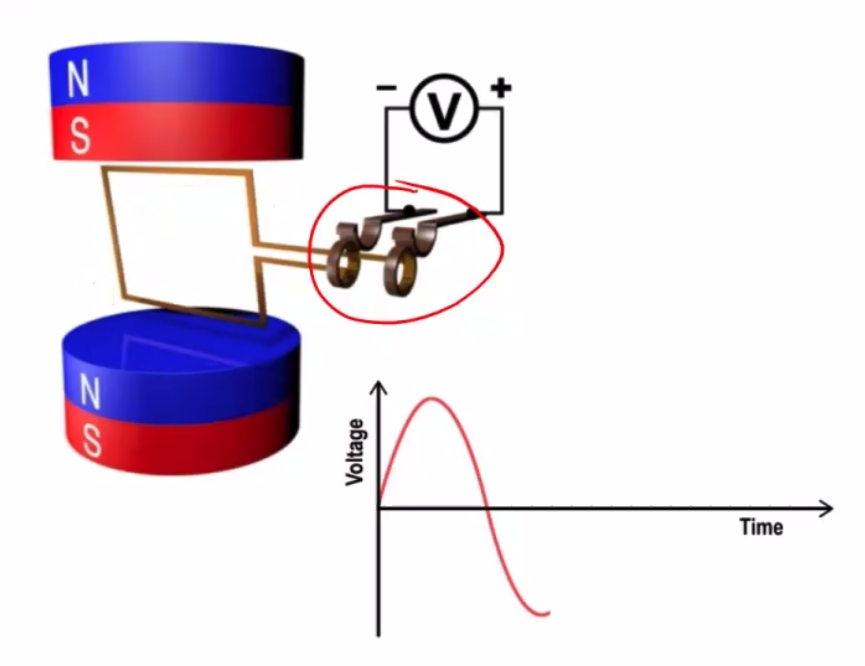
- Single phase AC generator
- Electricity generated according to:
- Size of conductor
- Strength of magnetic field
- Speed / rate of cutting magnetic flux.
- Gauge is still a voltmeter
- Still have line loss issue
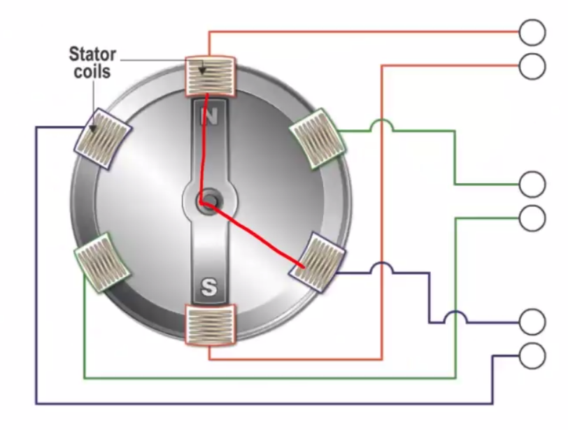
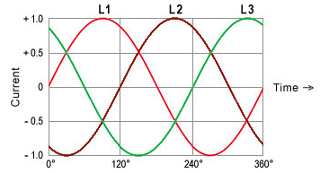
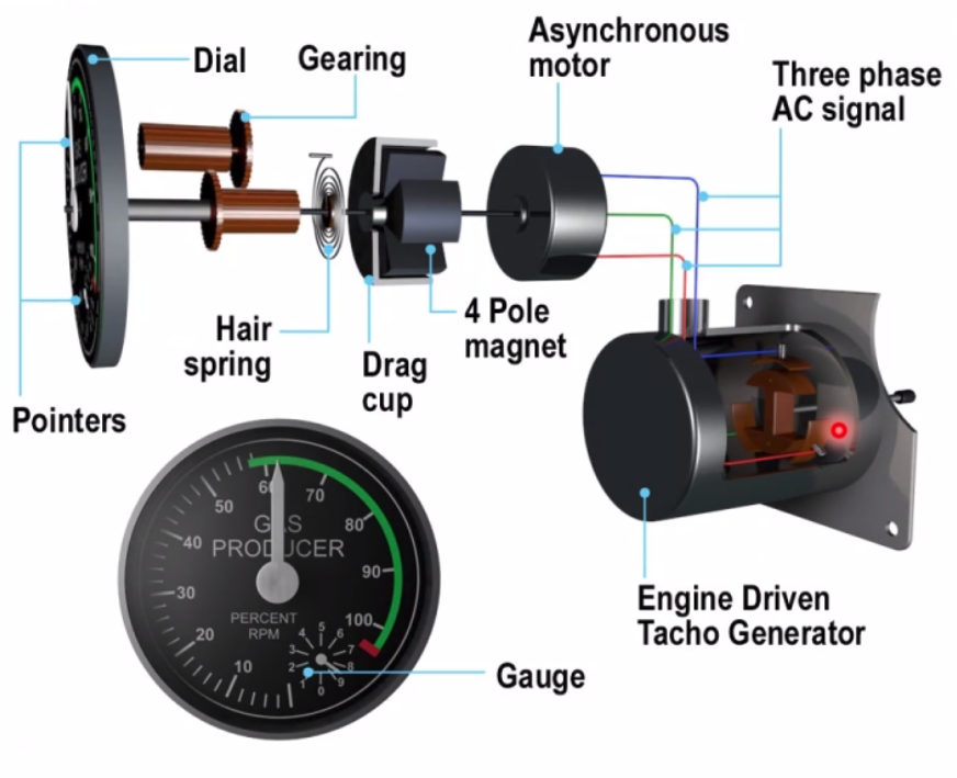
AC Three Phase Tachometers
- aka ‘Induction Tacho’
- Output is three phase - frequency is proportional to RPM
- Image driving away from a radio mast - still hear the radio because it measures frequency and not amplitude
- Indicator is a 3 phase motor driving a drag cup
- No line resistence
- No sparking/arcing
Electronic Tacho (AC Phonic Wheel)
- Toothed ferromagnetic wheel
- passes coil of wire
- generates single pulse of AC
- counts the pulses of RPM
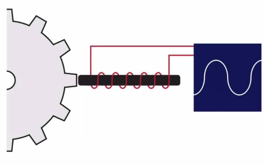 Rectifies the single AC current to a square wave of 1 / 0
 Easier for EFIS, Also provides RPM to FADEC, Sine wave rectified to square wave
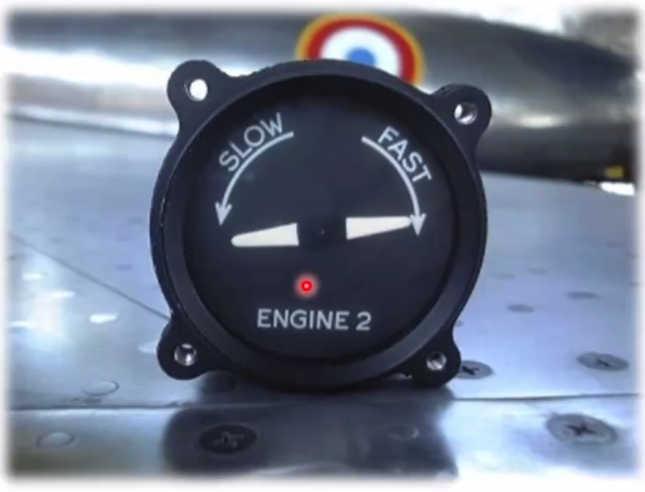
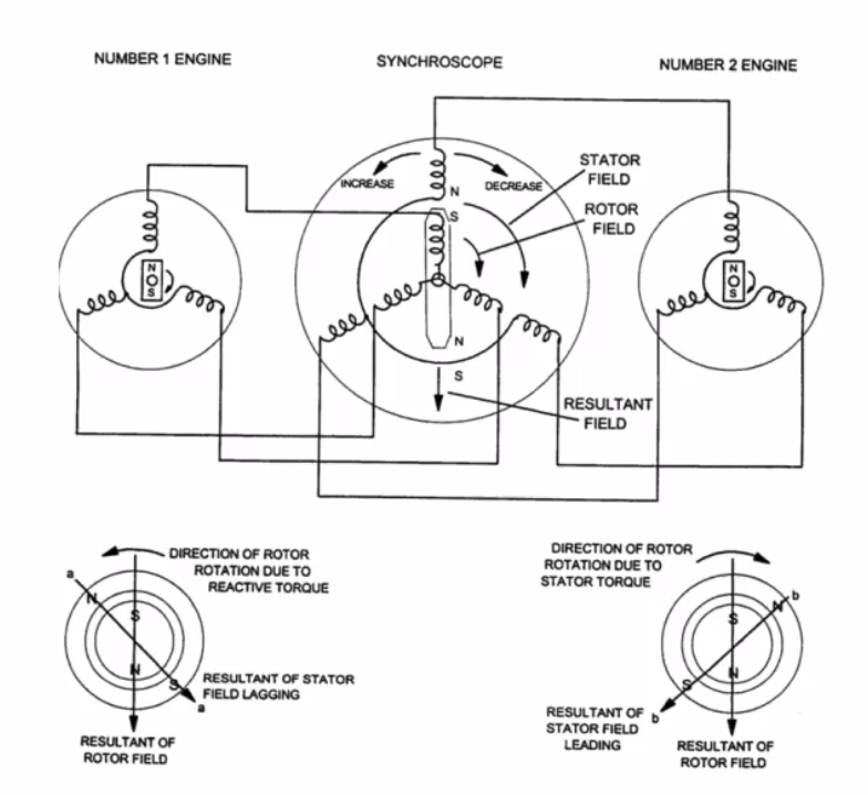
Synchroscope
- synchronises engines
- reduces noise/fatigue
- works directly from RPM signal
- Slave engines set to master RPM
- stator connected to slave
- rotor connected to master
- Modern AC automated
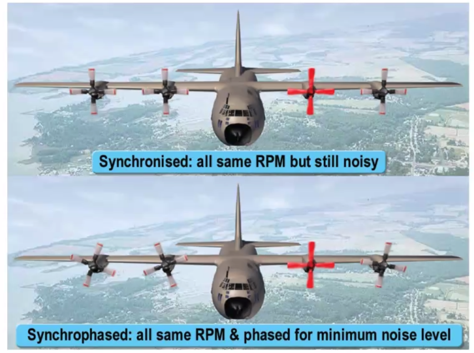 Synchroscope
- Synchronised - same RPM
- Noise levels still quite high
- Synchrophased - blade positions
- No 2 Engine shown as master
Pressure Sensors
- Gauge Pressure - calibrated against atmospheric
- Absolute Pressure - calibrated against a vacuum
- Absolute = Gauge + Atmospheric Pressure
- Direct or Indirect indications
- Elastic Pressure Sensing
Elastic Pressure Sensing
- Capsule type
- Low Pressures
- More Sensitive
- More Durable
- single capsule - low pressure instrument
- bellows - medium pressure instrument
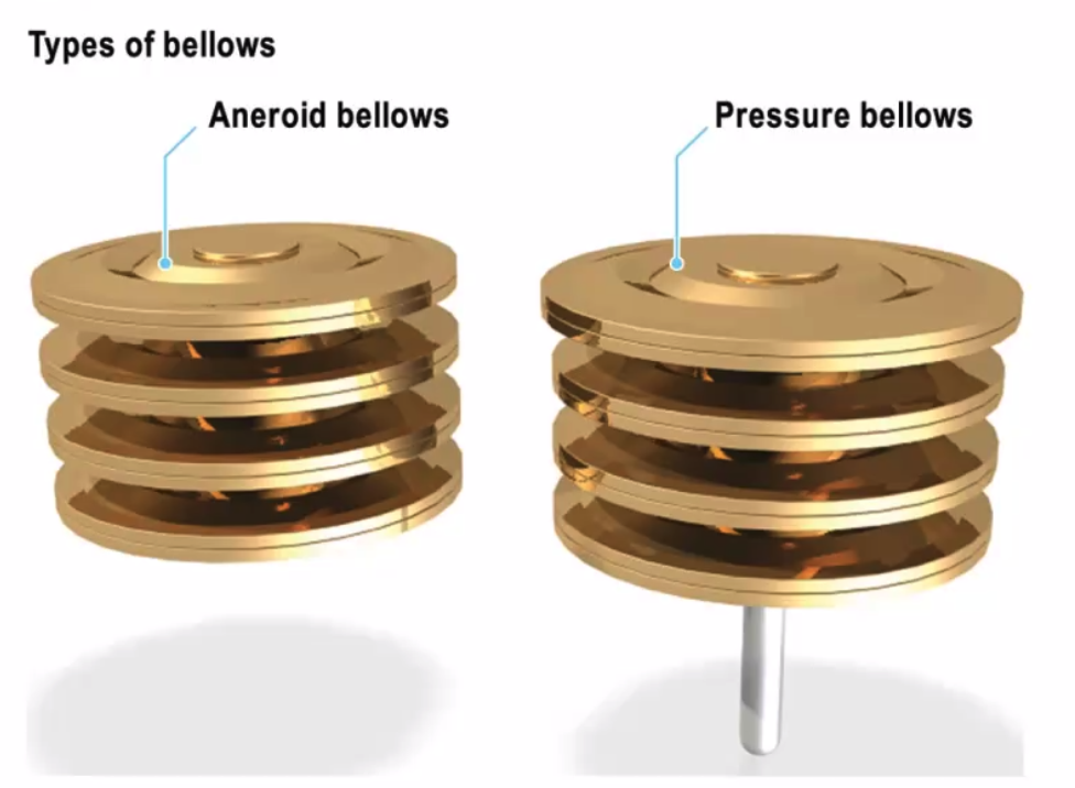
Aneroid bellows - does not have an intake so atmospheric pressure alters the shape of the bellows Pressure Bellows - has an intake so that the pressure inside alters that shape of the bellows
Manifold Absolute Pressure - important because it measures absolute
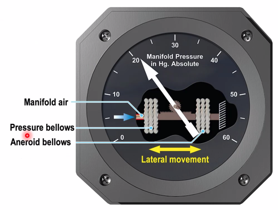
Aneroid Bellows + Pressure Bellows = Absolute Pressure
Aneroid bellow measures ambient Pressure bellows measures suction.
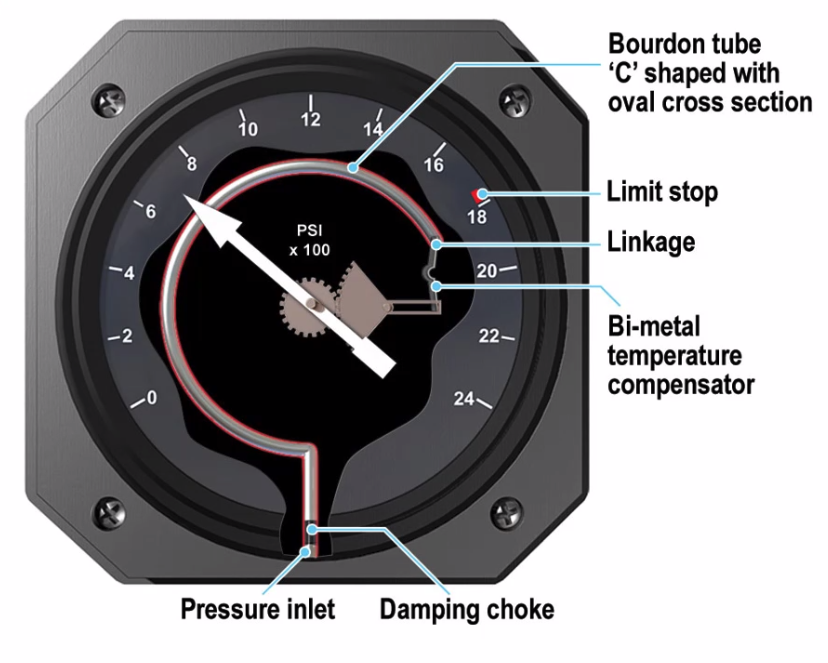
Bourdon Tube
- C shaped with oval cross section
- Measures high pressure - tries to straighten out under pressure
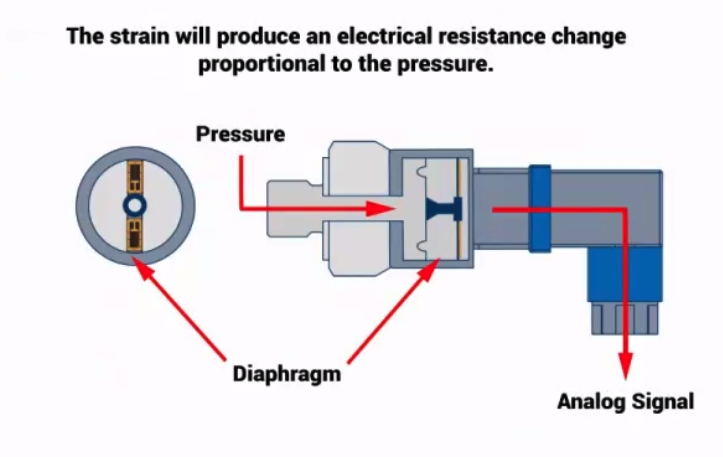
Transducers - not in LO but is the modern pressure sensor and HAS popped up in the exam.
- Mainly on hydraulic pressure systems
- It pushes against a matrix which changes shape, the flow of electricity over this new shape determines the resistance (?) and change of voltage
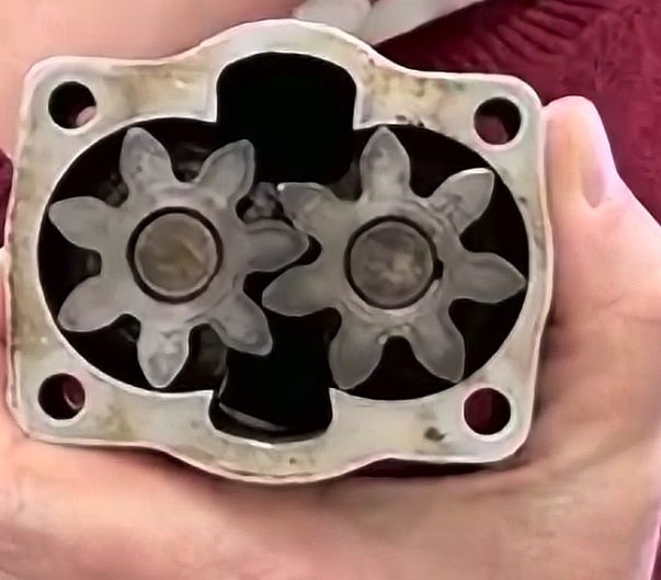
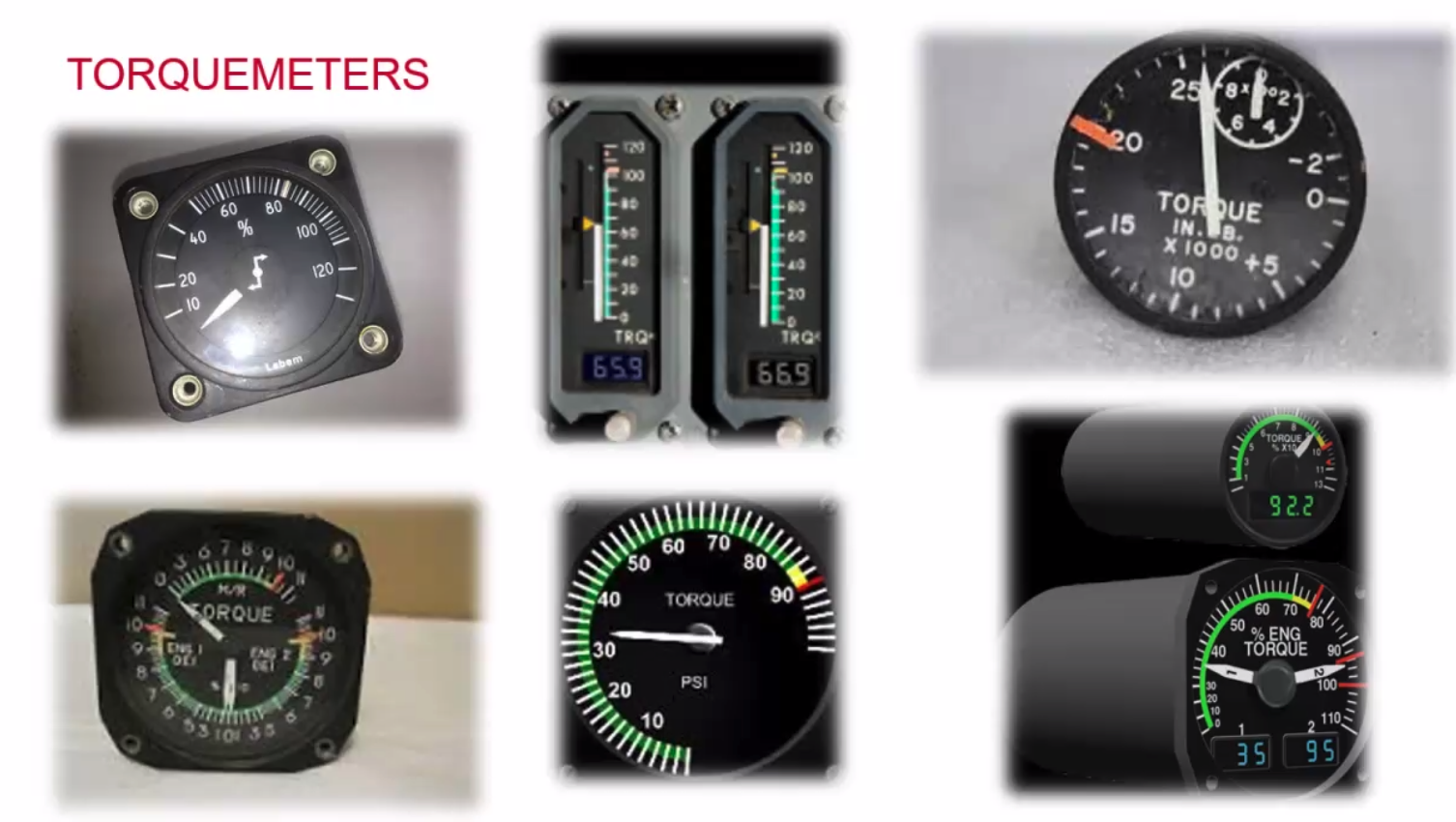
Torquemeters
- Measures twist
- Oil pressure type
- Spur cut gears have no side force
- bevel cut gears exhibit a side force.
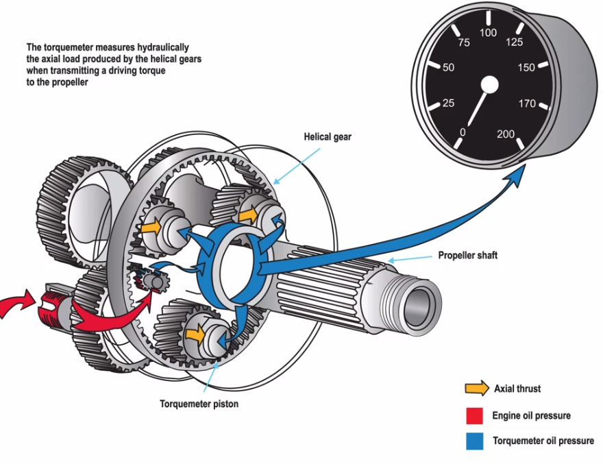
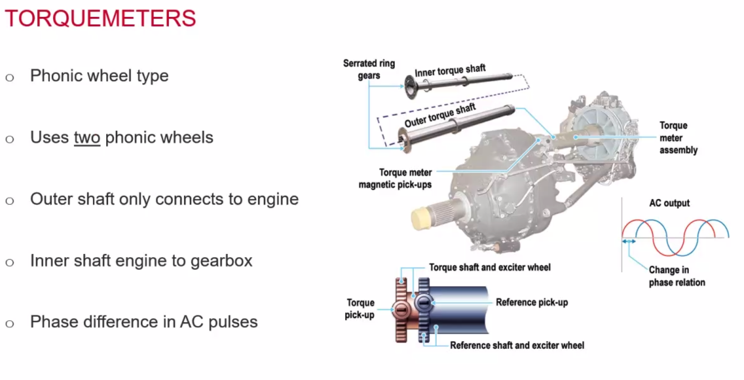 Expresses twist / torque in shaft
==Power = Torque x RPM==
Vibration Meter
- No indication of the values, just an indication.
- Uses two accelerometer -
- Magnet on a spring - measures relative amplitude, frequency is filtered and amplified. Based on where the ball / spring is.

Fuel Measurement
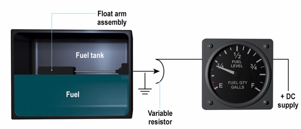
Float Type Gauge (Volume measurement)
- Float attached to rheostat
- Changes current flow
- Gauge is an ammeter
- Accurate when almost empty
- Volume Measurement
- Affected by attitude
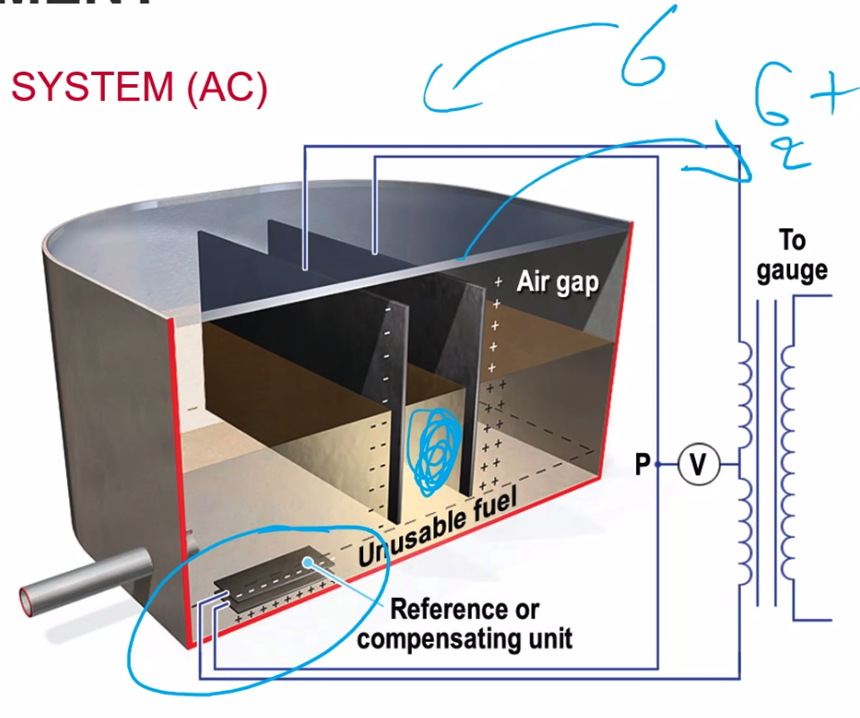
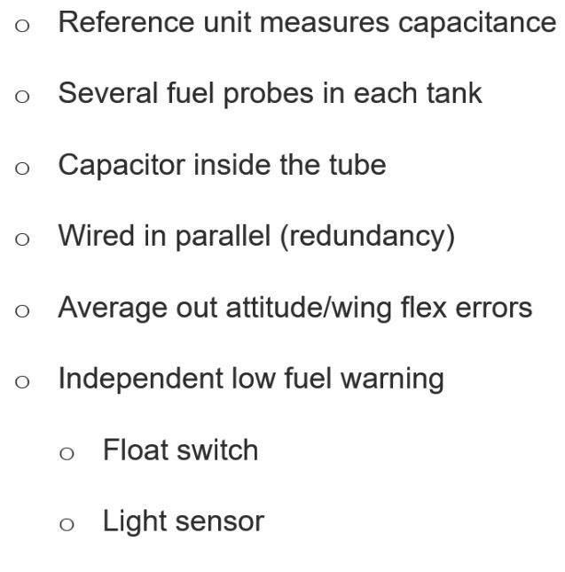
Capacitance Gauging System (Mass Measurement)
- Depends on air gap, size of gap and dielectric
- Charge depends on
- size of plates
- distance between the plates
- value of the dielectric
- Current drives a torque motor which drives the gauge
- Volume measurement
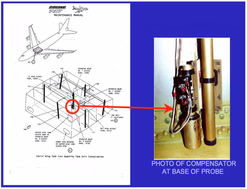
- Compensating unit gives mass
- Temp rises?
- Volume increase, density decreases
- dielectric constant reduces
- gauge reads the same
- Measured in Farads (Capacitance)
- Dielectric values
- Air = 1
- Fuel = 2
- Water = around 81
Capacitance = E x A / D
E = Dielectric Value A = Area of the plates D = Distance between the plates
A and D are fixed by design
E varies according to the substance.
Fuel Flow Measurement
- Volume Flow
- Litres per hour
- Gallons per hour
- Mass Flow
- Kilgrams per hour
- Pounds per hour
- Fuel Used
- Flow integrated over time
- Fuel flow measured just before the engine
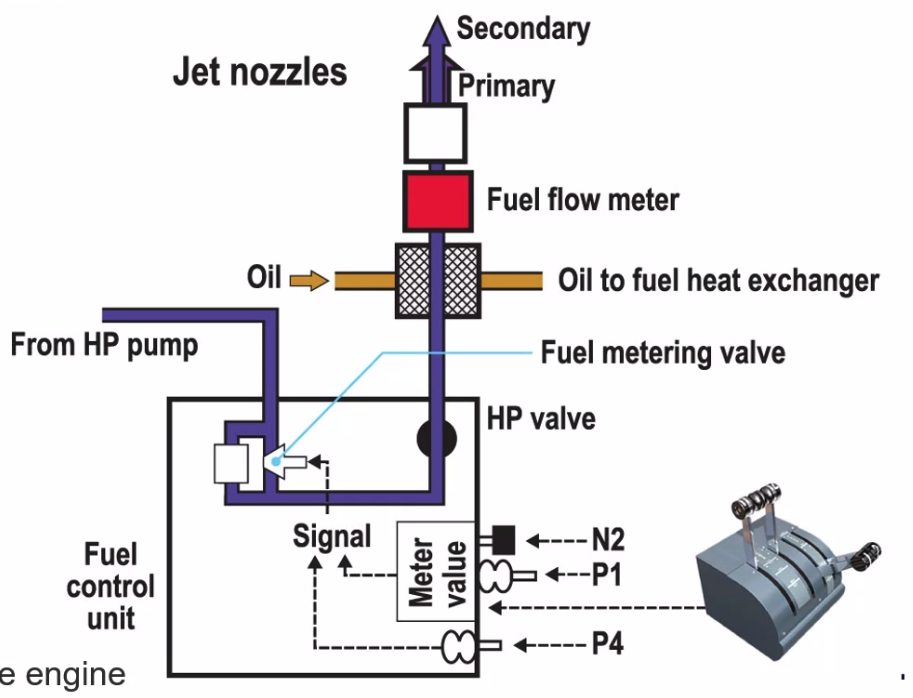
Why do we suck fuel rather than blow it?
- If we blow and theres a hole in the pipe it will leak. However if we suck it just sucks fuel and doesn’t leak fuel. Think negative pressure.
Fuel flow measurement - volume / AC
- Impeller turns a small magnet which pass an induction coil which generates pulses of AC.
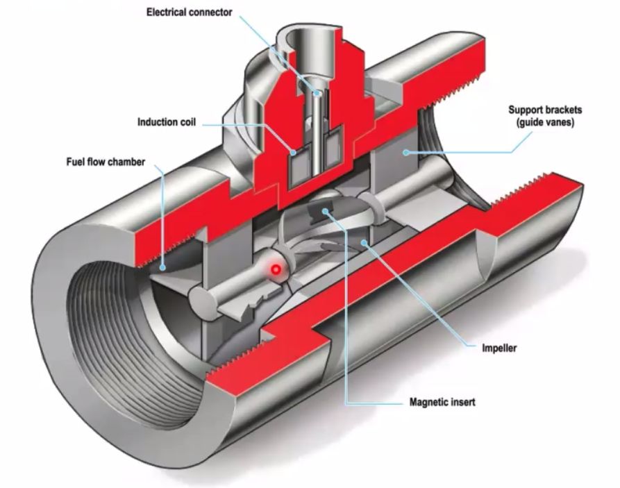
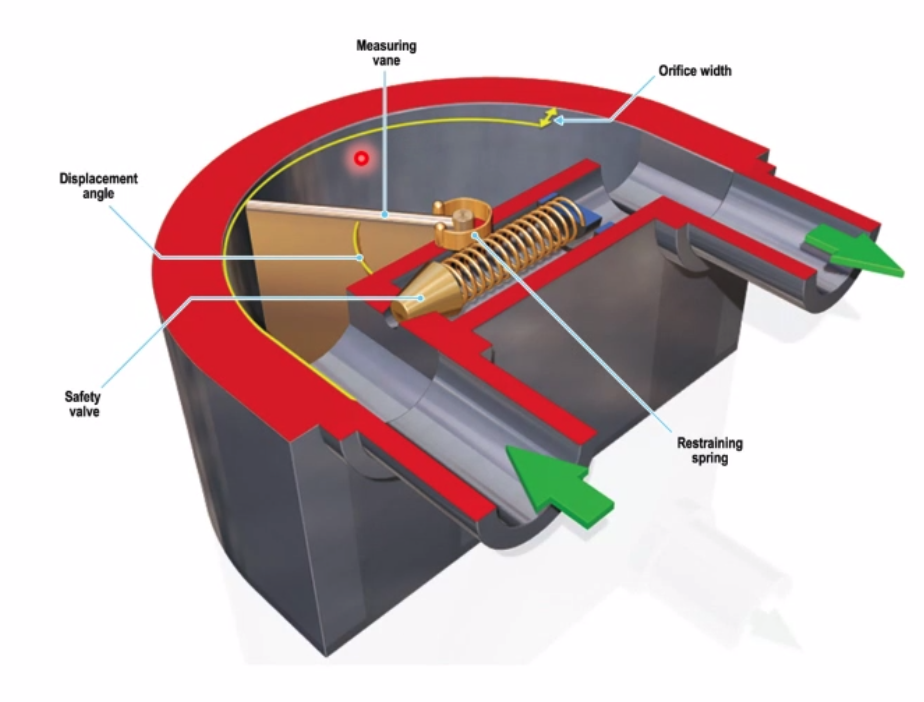
Also a mechanical version:
- Angle is measured of the door which measured the flow. Includes a PRV incase door jams.
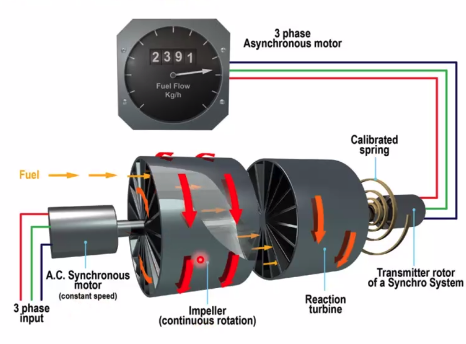
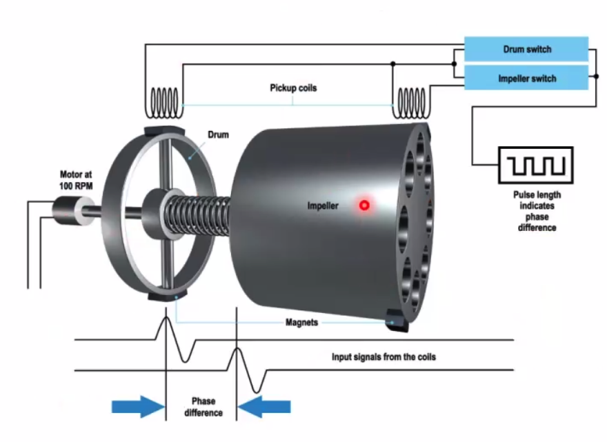
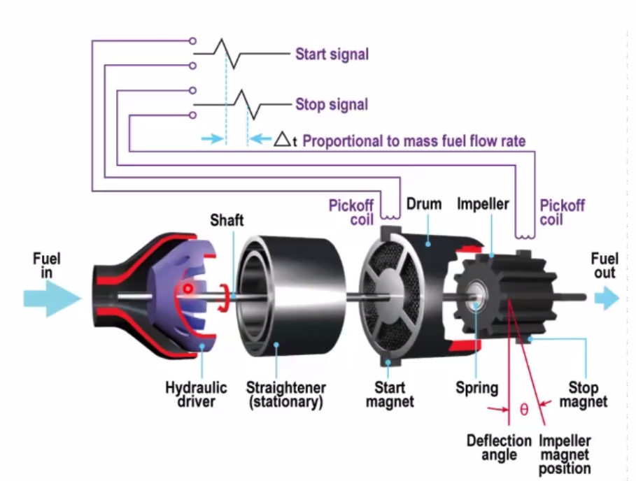
Mass Flow / AC
- AC motor drives impeller
- Swirl gives angular momentum
- Reaction turbine senses momentum
- Requires Power
Electronic Measurement
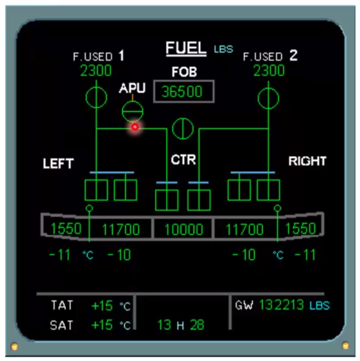
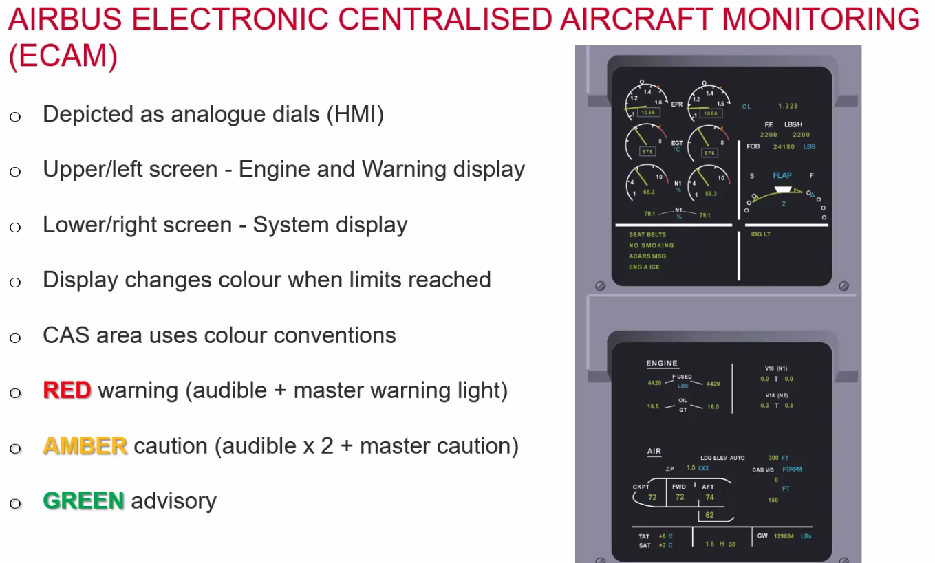
Fuel indications - Airbus ECAM
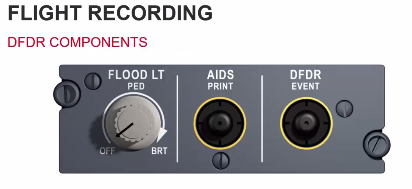
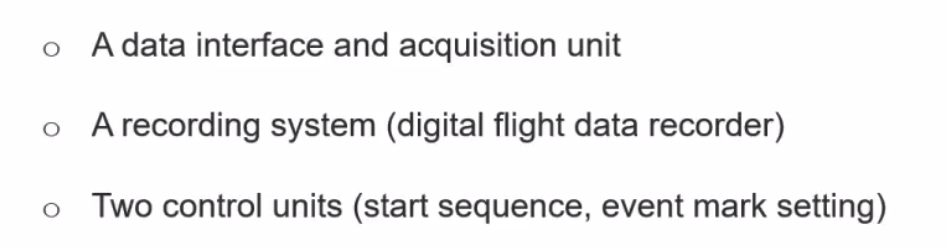
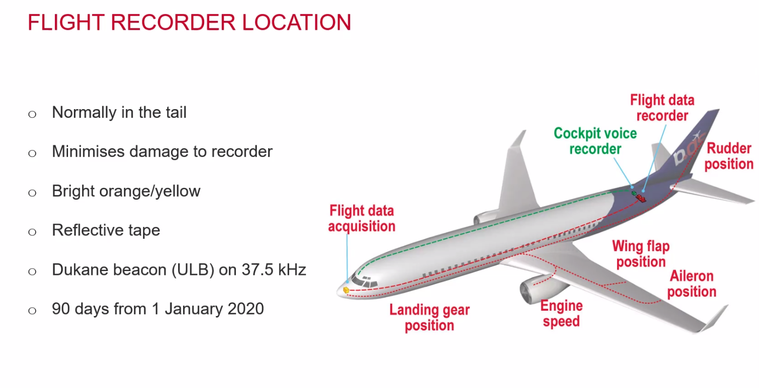
Flight Recording
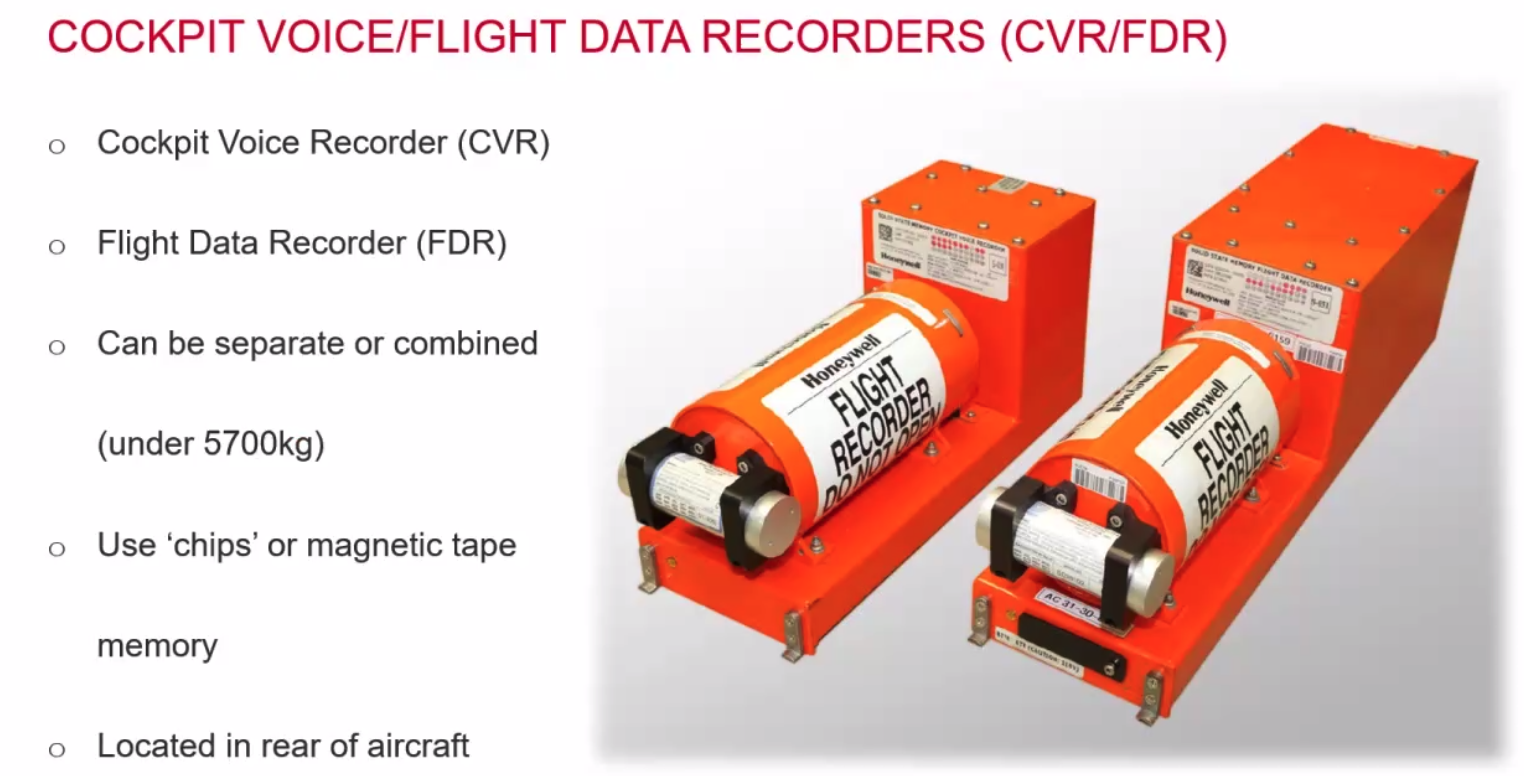
- Solid state memory mounted in a shock resistant case
- underwater locating beacon good for 3 miles / 90 days
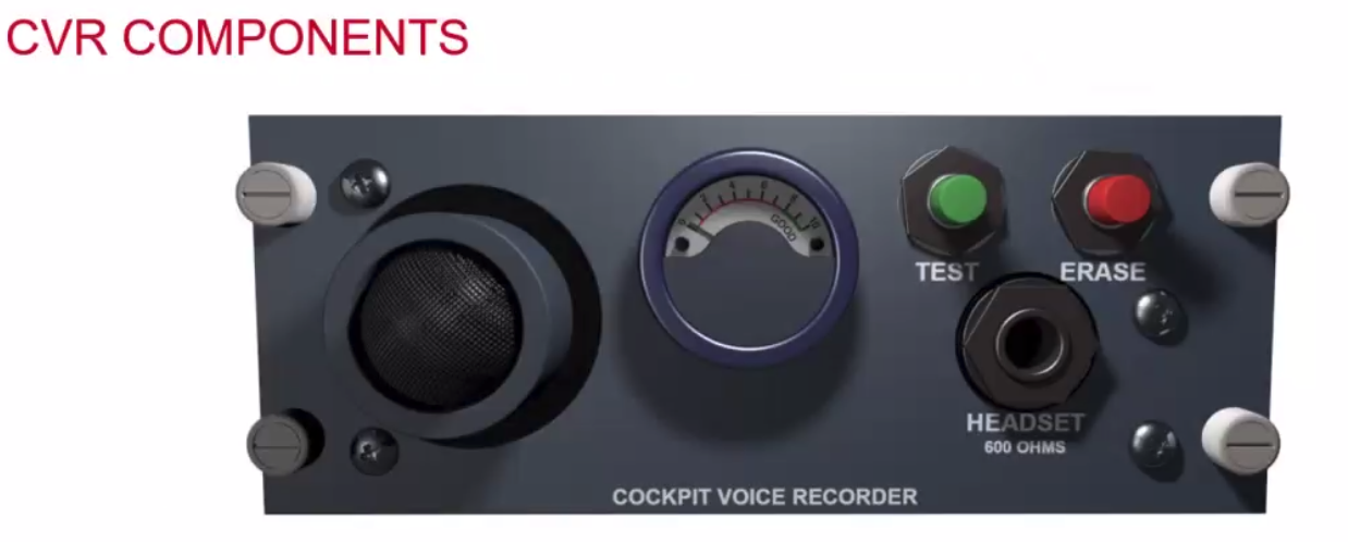
- Cockpit area microphone
- control unit with auto/on, test, erase, and a headset jack.
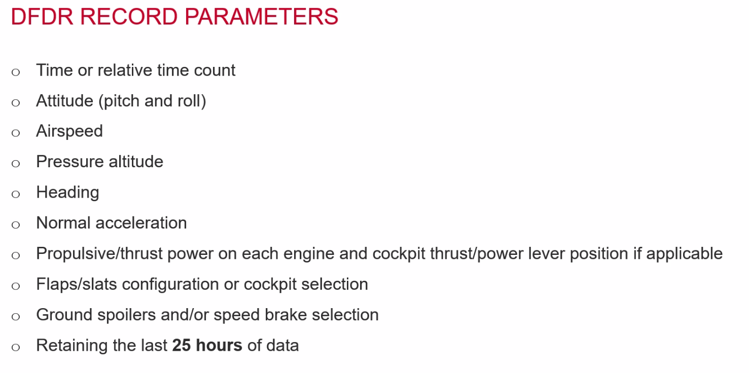
Missing - Yaw data is excluded.
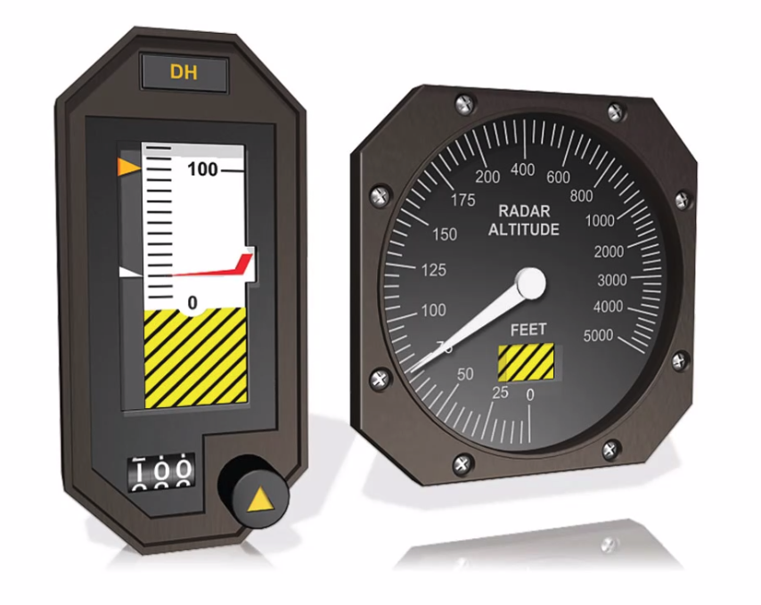
Radar Altimeters
- Calibrated to read 0 on the ground - account for the landing gear and the length of the cables
- Works in SHF, Centimetric band, Modulates from 4200 to 4400MHz
- Frequency difference indicates true height
- Accurate to +/- 2ft up to 500ft
- Higher sweep rate at lower altitudes
- Accurate to +/- 1.5% above 500ft
- Req for Autoland CAT III
- GPWS
- TCAS
Cockpit Displays:
- vertical scale or round dial
- Must indicate 0 - 2500ft
- May indicate more
- Bugs to set decision height
- Expanded scale closer to the ground
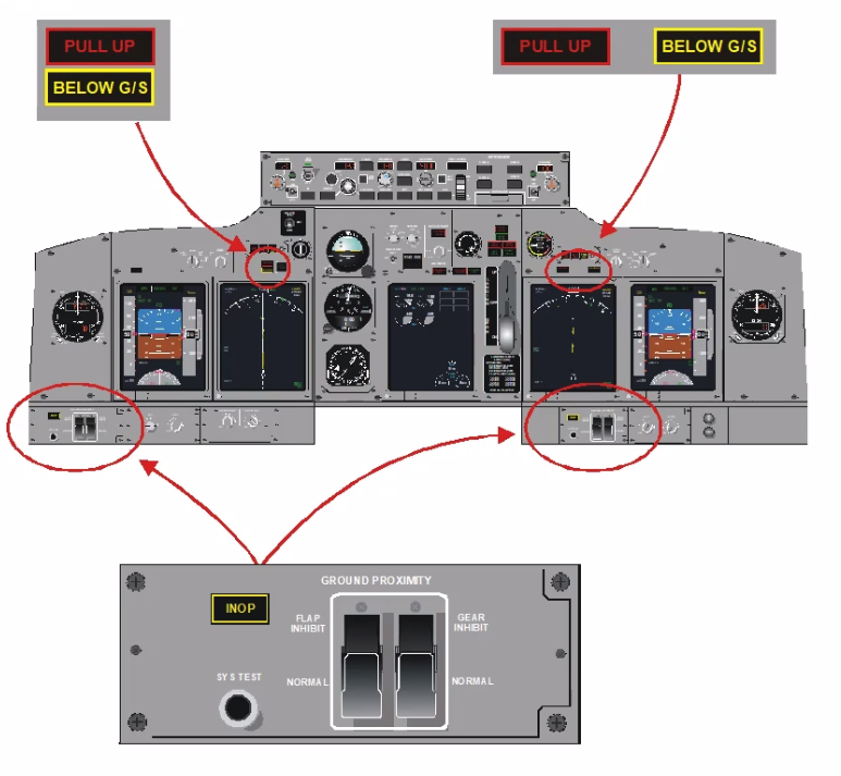
Ground Proximity Warning Systems
- Four variants
- GPWS
- EGPWS (Enhanced GPWS)
- TAWS (Terrain Awareness System)
- HTAWS (Heli TAWS)
GPWS - ICAO annex 6
- GPWS on all aeroplanes on public transport > 5700kg, >9 passenger seats (greater than 9 doesnt include 9, so must be 10 or greater)
- System must provide distinctive audio signal, and may have Visual Alerts
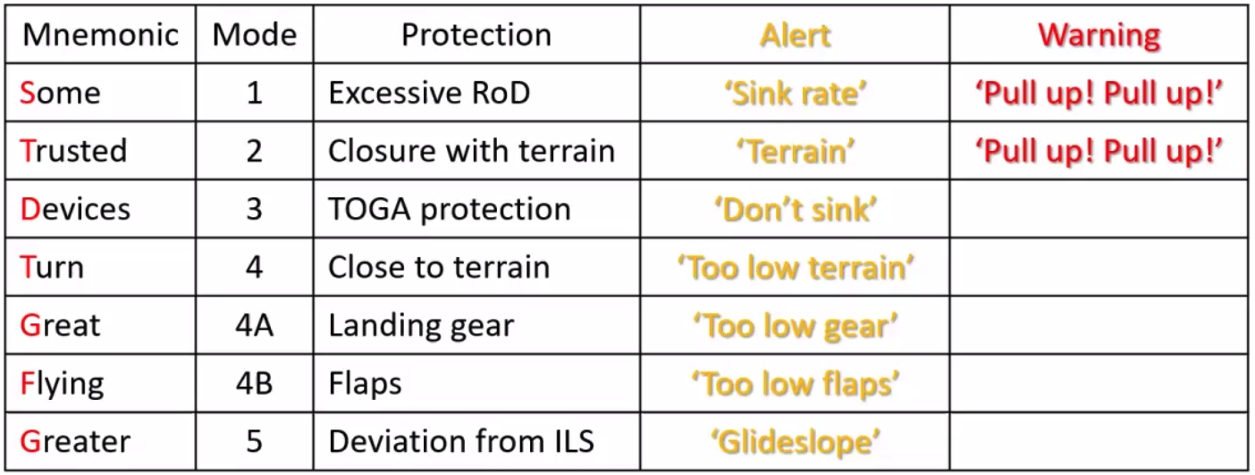
- 5 basic modes of operation
- May have additional callouts
- Height
- Bank
- Windshear
- Aeroplanes greater than 15000kg and over 30 passenger seats MUST have EGPWS
GPWS Inputs RAF Navigator R - Rad Alt A - ADC (Pressure Speed, Mach) F - Flaps, Gear N - Nav Receiver (ILS Glideslope)
GPWS Warnings and Alerts
- Range 2500ft to 50ft
- Hard Warning - red, requires immediate climb
- Soft Alert - yellow, requires a corrective response.
- Flap and Gear alerts may be inhibited
Not taught but found elsewhere online
Mnemonic: ==STD GirlFriend? Good Man Be Wrapped!==
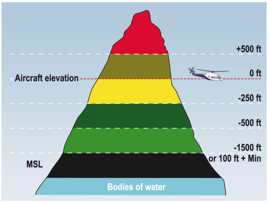
Enhanced Ground Proximity Warning Systems
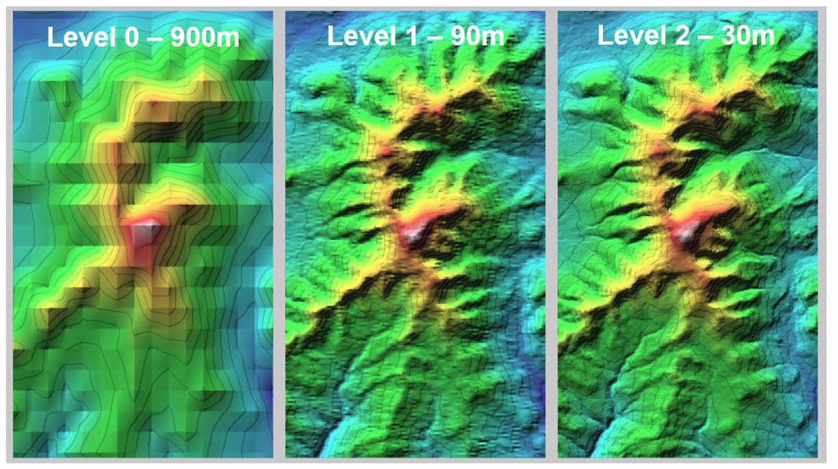
- World Terrain Database
- No expiry date for validity
- Obstacle Database
- 28 days
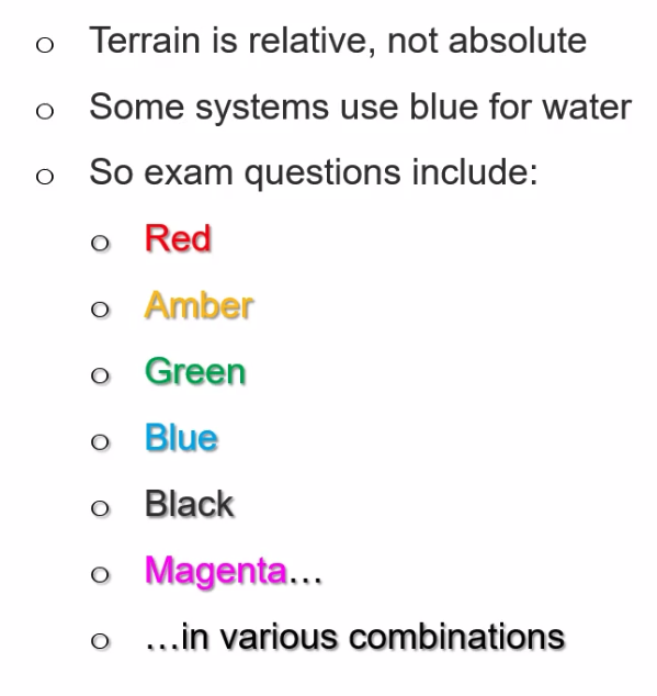
- Display uses mainly Green, Amber or Red
- Amber, Red - may not be able to avoid terrain
- Magenta - terrain not in the database (think large expanses we don’t go to - Sahara, Siberia etc)
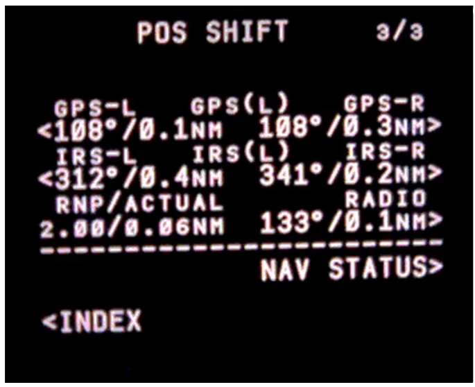
- Positional accuracy essential
- Required Navigational Performance
- Actual Navigational Performance
- RNP10 = accuracy within 10nm either side of track
- RNP0.3 = accuracy within 0.3nm either side of track
==Q. When installed, a TAWS must be coupled to:== A. A three-dimensional world terrain database
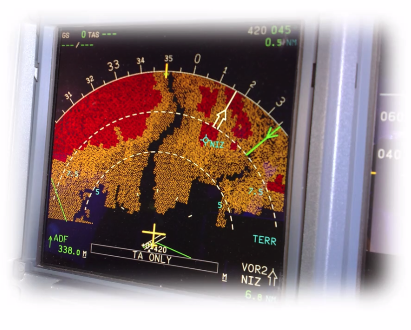
- TAWS and WXR mutually exclusive, use similar colours. Must check the TERR in blue to determine which is which.
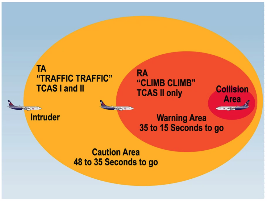
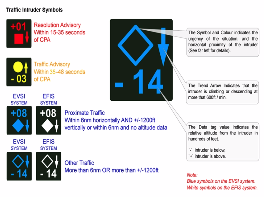
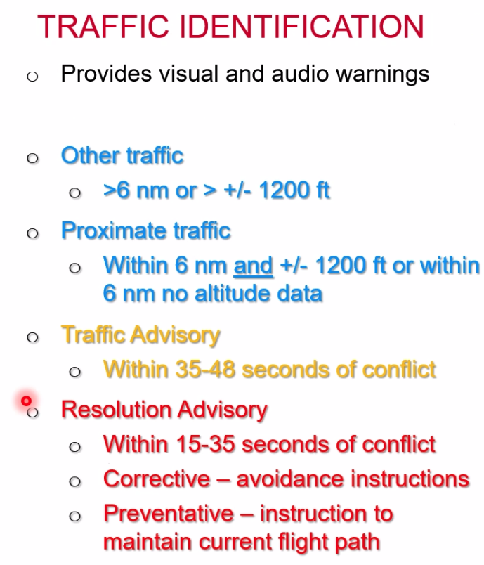
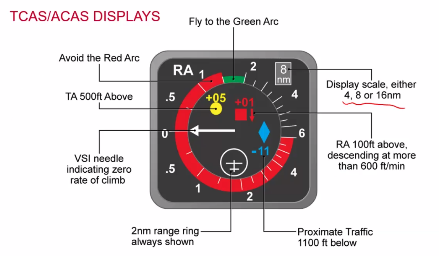
Traffic Collision Avoidance Systems
-
Transponder based system
- transmits an interrogation
- responds to an interrogation
-
TCAS 1 = Traffic Advisory
-
TCAS 2 = Resolution Advisory
-
Vertical Separation only
-
Lateral not yet accurate enough
-
EU Ops Requirement
- Passenger aircraft with over 19 seats and 5700kg TOM
-
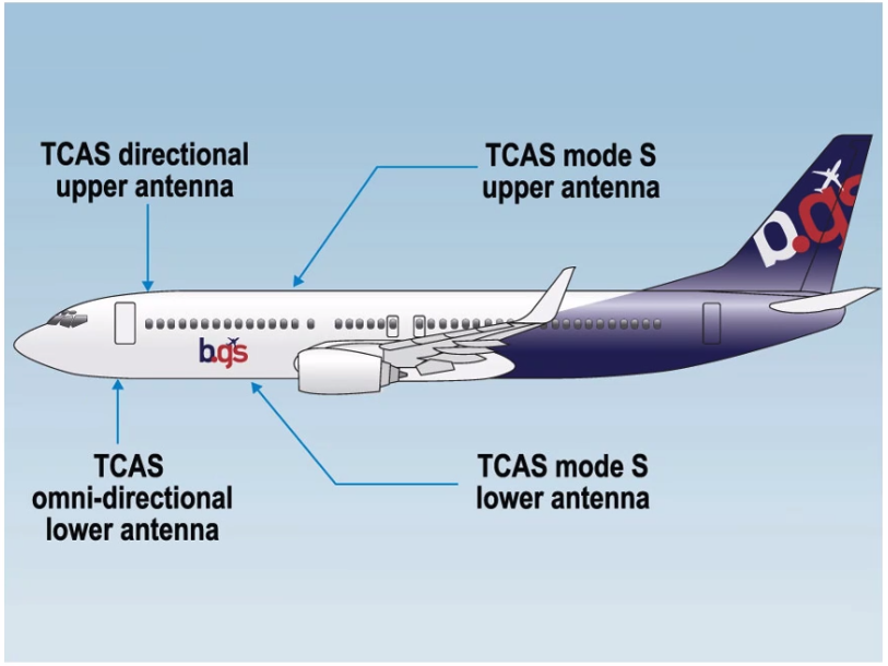
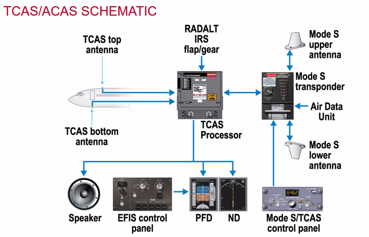
Inputs:
- S - Mode S Transponder
- C - Configuration of aircraft (flaps/gear)
- A - Air data computer
- R - Rad Alt (No RA below 1000ft)
- I - Inertial Reference System
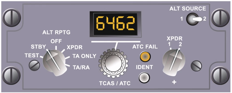
Q. Why would you use TA only? A. Might not have the performance to climb
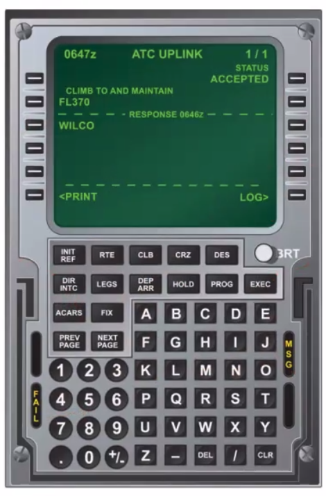
Data Links
- ACARS (Aircraft Addressing & Reporting System)
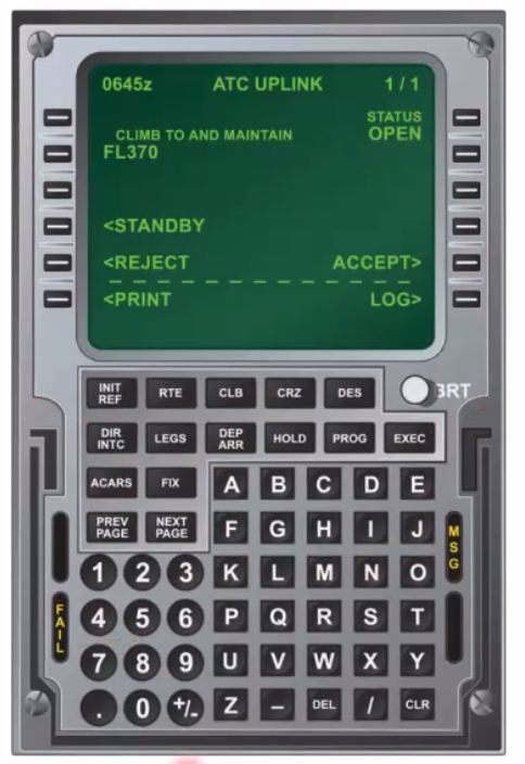
- CPDLC (Controller Pilot Data Link Communication)
- ADS-B (Automatic Dependant Surveillance Broadcast)
- ADS-B In - Receives data from ground stations
- ADS-B Out - transmits data from aircraft
- FANS (Future Air Navigation Systems)
- D-ATIS (Datalink transmitted ATIS messages)
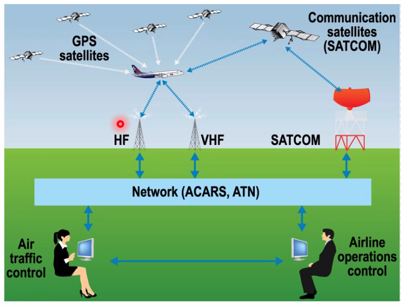
Onboard Datalink Comms
- Multi function control display unit
- Communications Management Unit
- Communication Unit (VHF HF Satcom)
- HF - slowest
- VHR - medium
- SATCOM/AMSS - fast
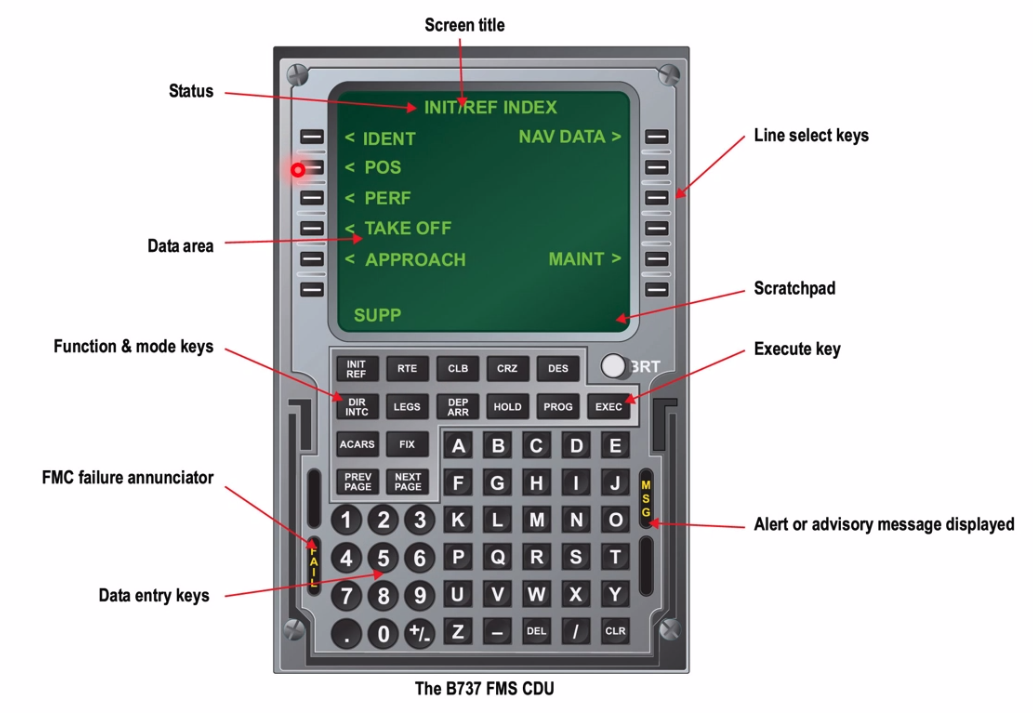
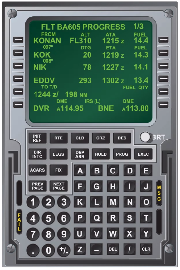
MCDU
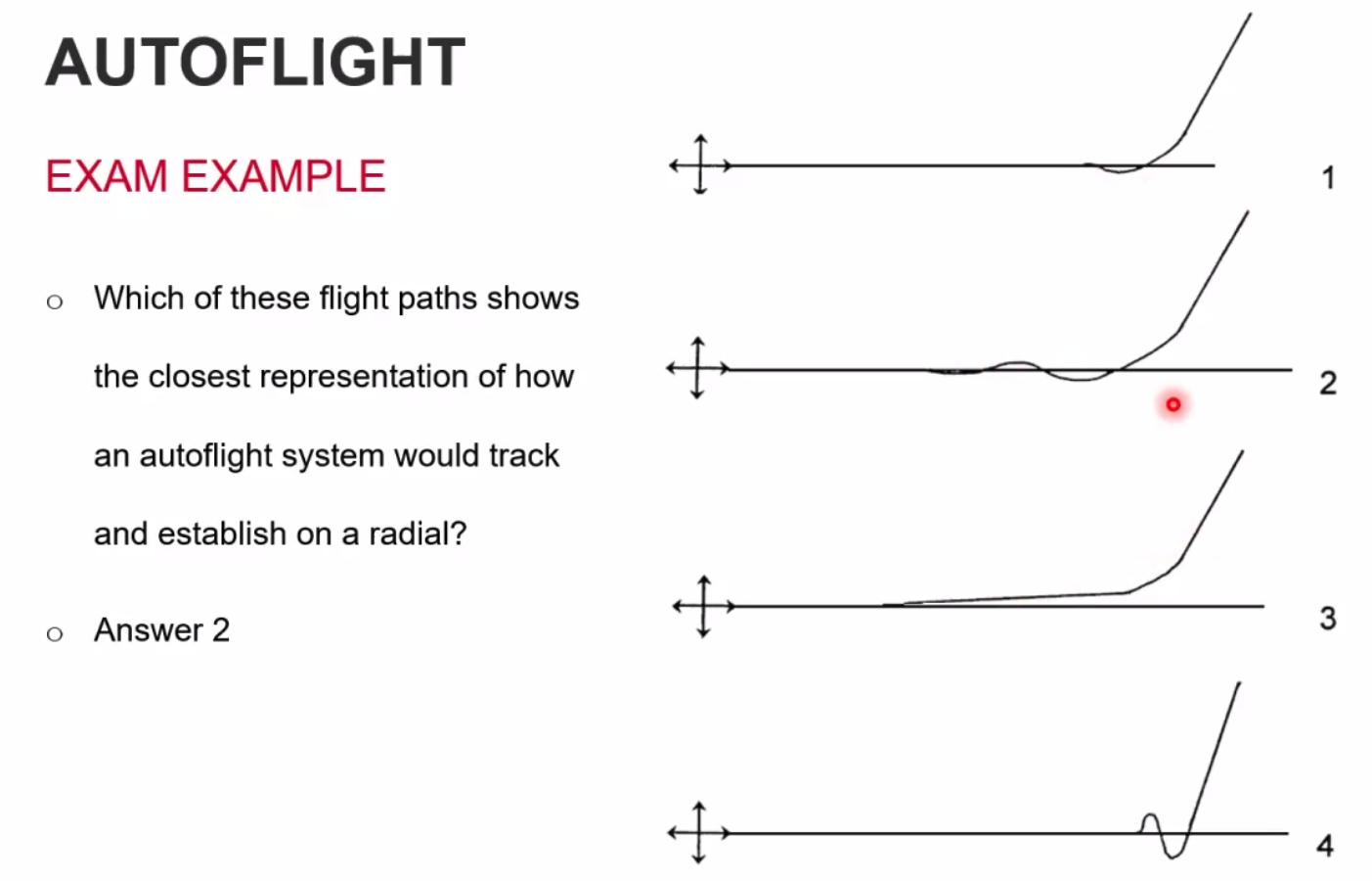
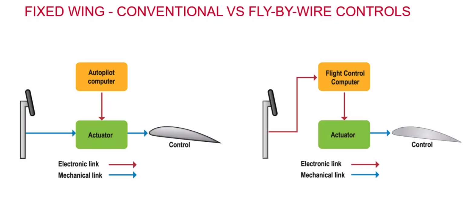
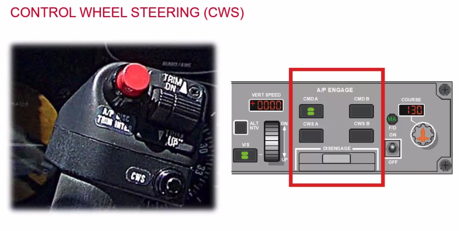
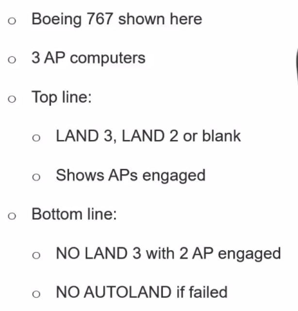
Autoflight
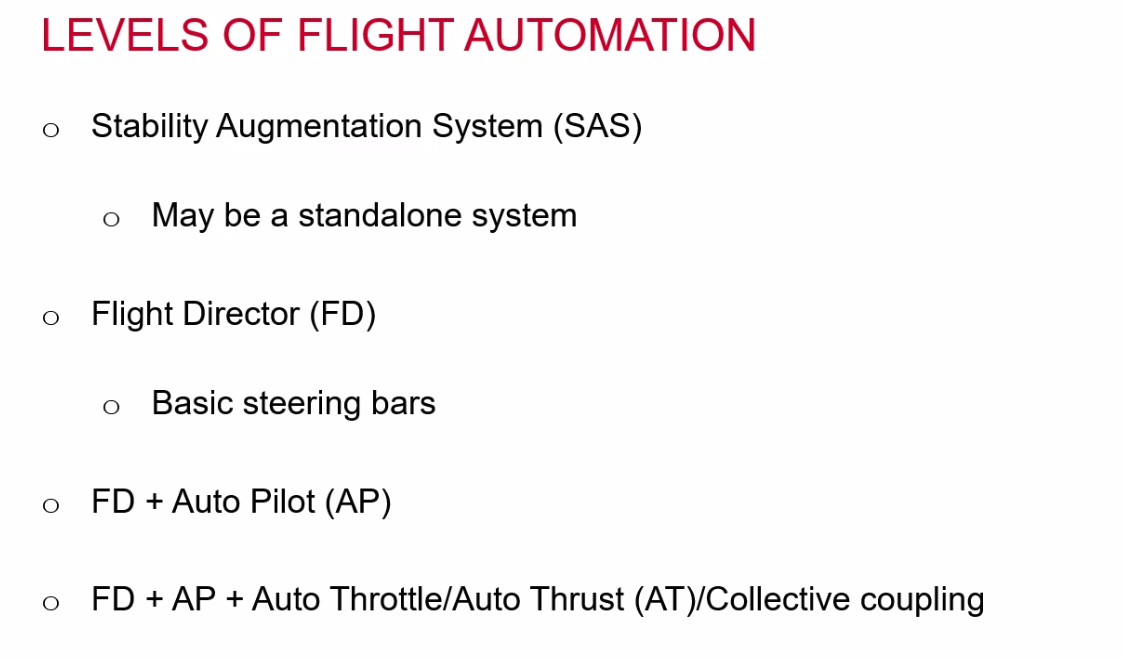
- FD + AP + AT + FMC
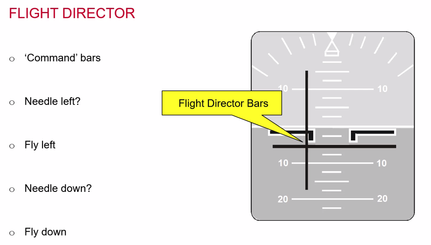
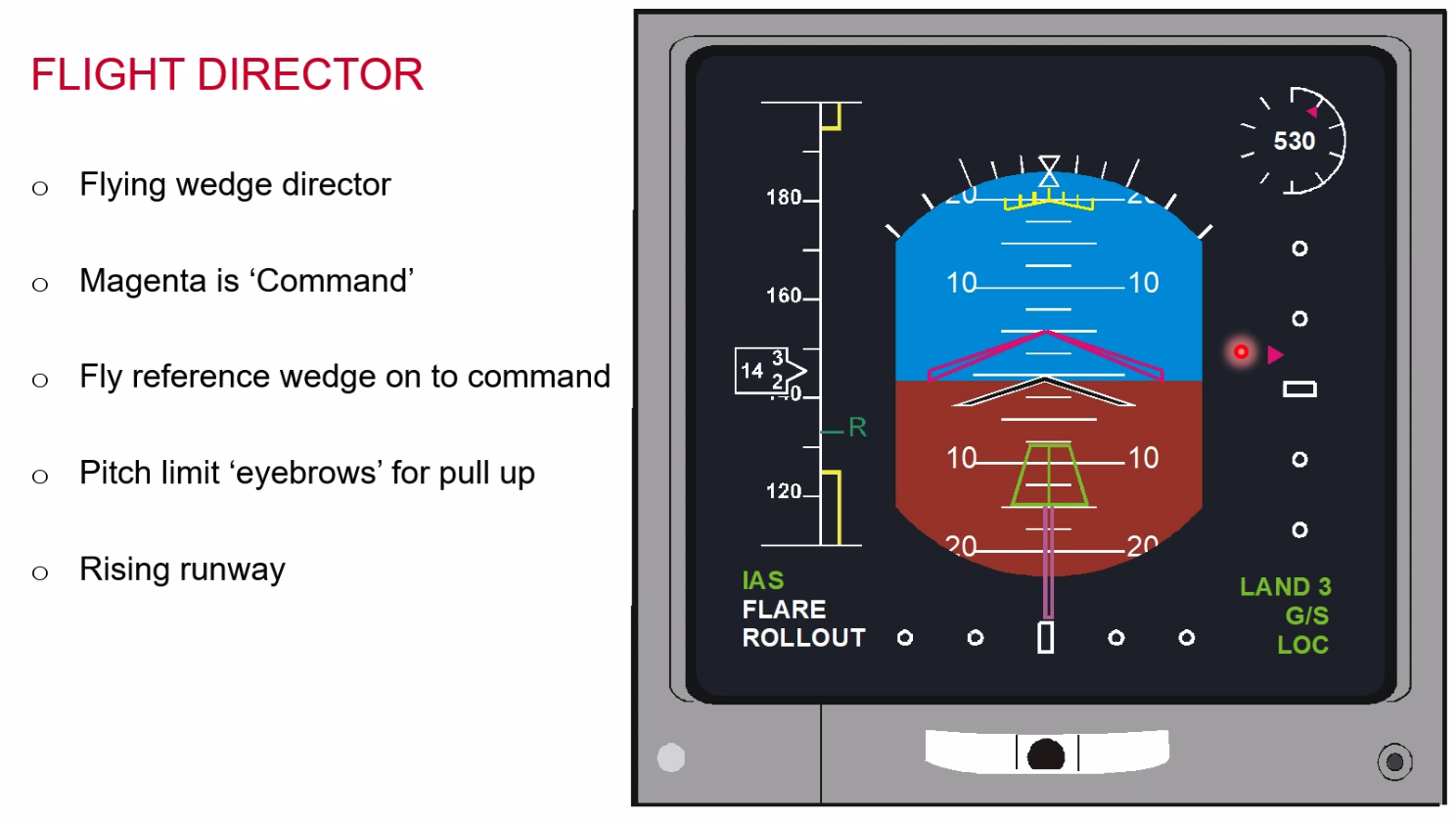
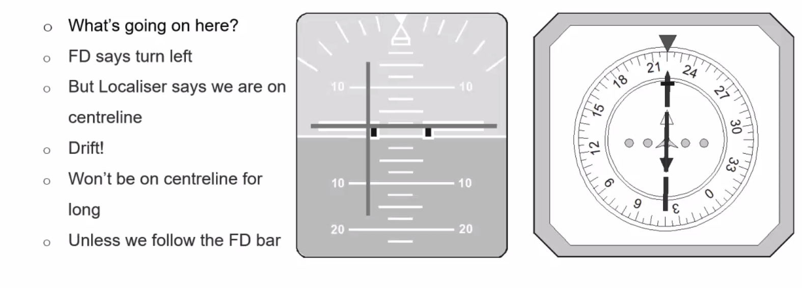
Flight Director - provides the instantaneous path to reach the selected radial
- on glideslope - bar and diamond centered
Basic Autopilot
- requirements for Single Pilot IFR
- Altitude Hold
- Heading Hold
- Stability system
- Stability & trim
- pitch trim as a minimum
Types and Levels of Controls
Stability
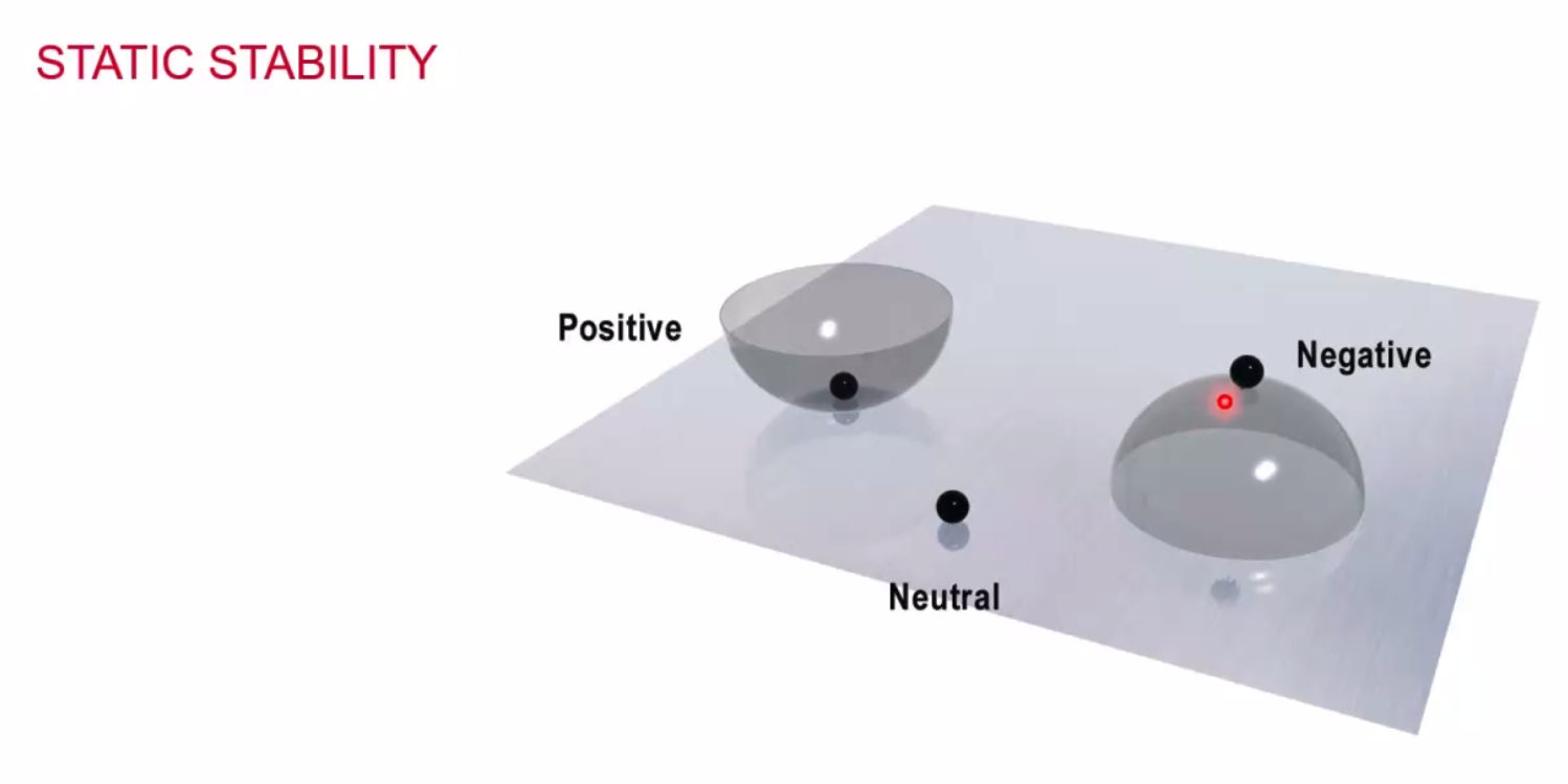
- positive static stability - hit the bowl the ball will return back
- negative static stability - hit the bowl and the ball will not return back
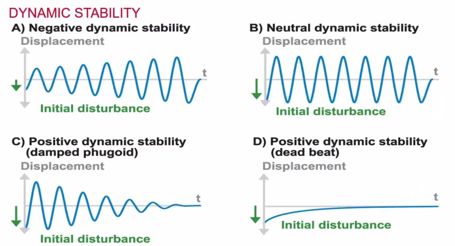
- Dynamic stability is impossible without static stability
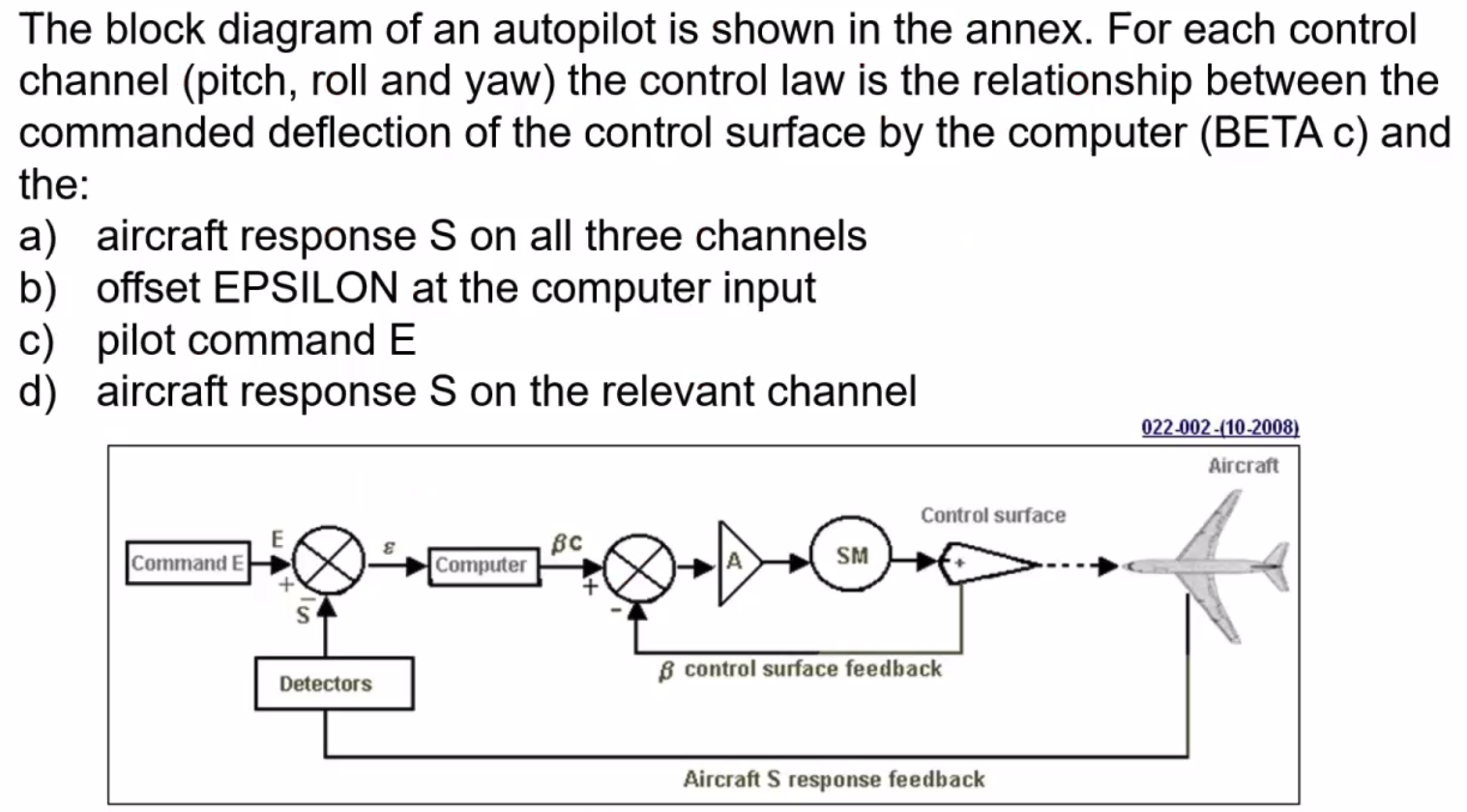
For Autoflight we need:
- Sensors - to detect altitude and changes
- Computers - to work it all out
- Comparator - to compare what we have with what we need.
- Amplifiers - to convert data into the signals
- Servos / actuators - to move the control surfaces
Horrible question - no longer in the exams, B is the answer.
 Autopilot engagement is inhibited if:
- Electrical supply faulty
- Roll control knob is not centred
- Synchronisation fault
- Attitude reference unit fault
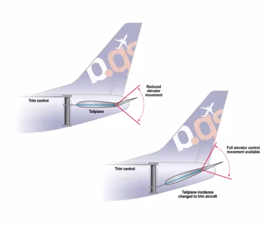
Mach Trim
- Only operates at high mach numbers
- shockwaves reduce downwash, increasing longitudinal stability, causing nose to pitch down,
Yaw Damper
- prevents Dutch Roll
- Aircraft with greater lateral stability than directional can suffer from a periodic motion called ‘Dutch Roll’
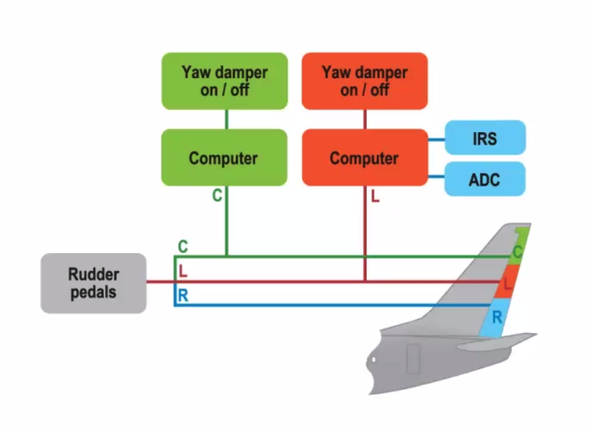
- Can be stand alone or integrated with another system
Autothrottle
- Maintains selected
- Airspeed
- Mach Number
- N1
- EPR
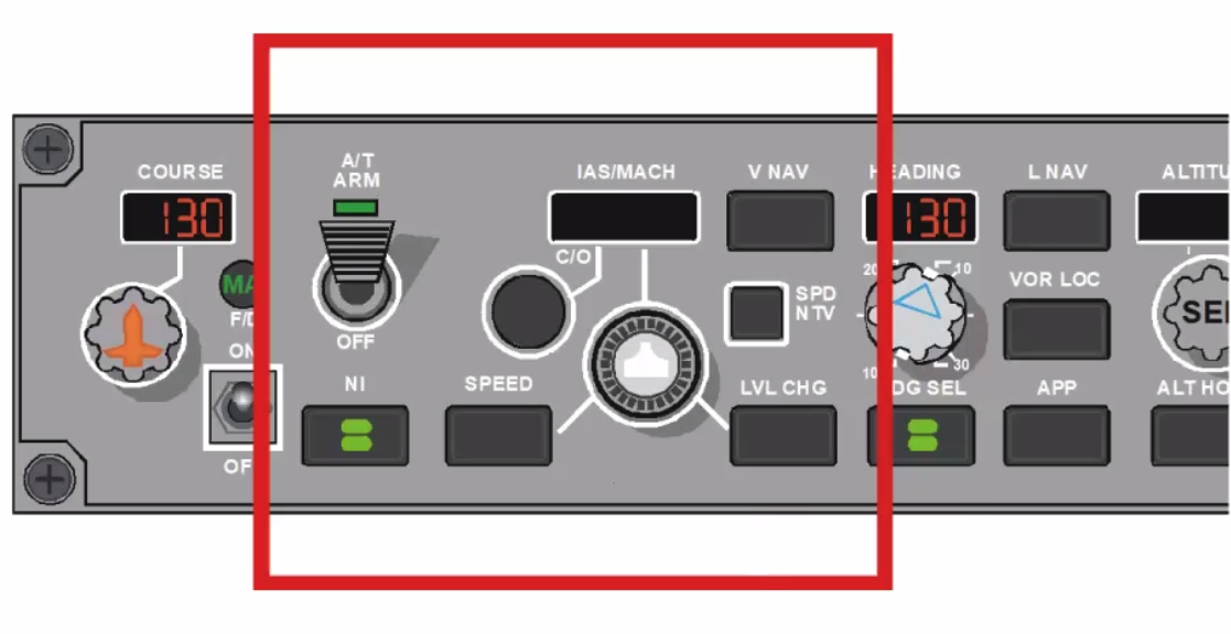
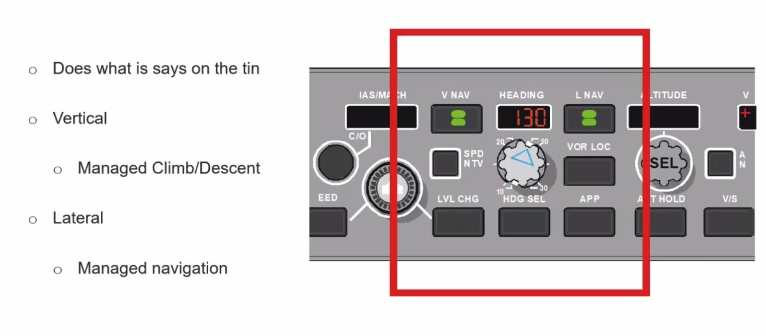
LNAV/VNAV
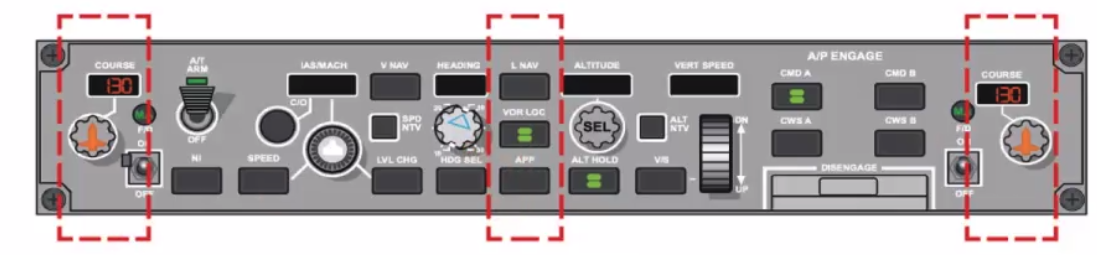
VOR & Localiser (VOR/LOC)
- Radial selected on rotary knob
- VOR LOC pushlight selected
- White - armed
- Green - engaged
- Automatically engages when valid signal received from VOR/LOC
- Captures and maintains the radial or centreline
LOC - Airfield, VOR - Elsewhere
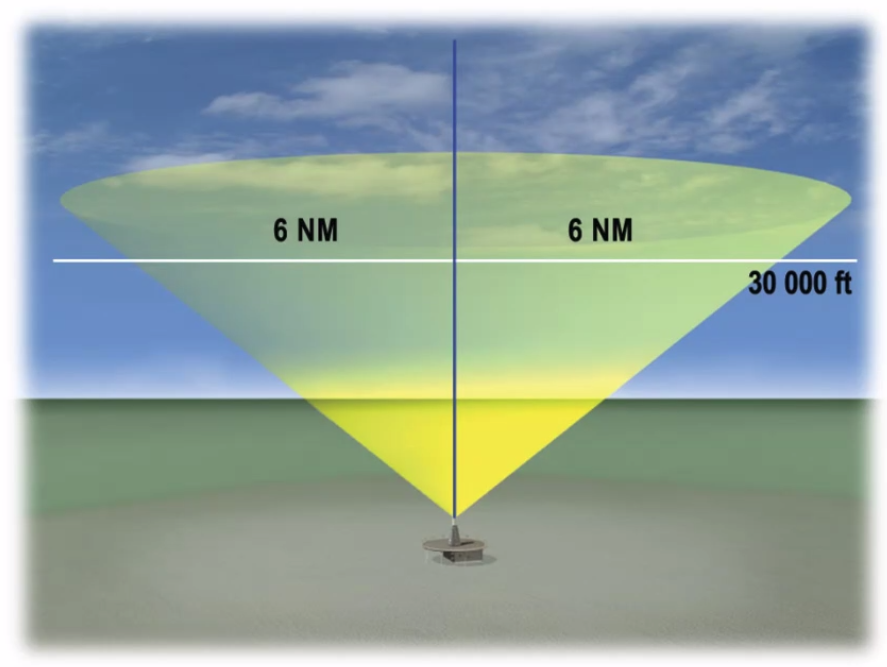
Cone of Confusion - Affects VOR and LOC, Over Station Sensor ignores confusing signals, AP switches to heading hold until leaving cone of silence, re-engages on reciprocal
Vertical Speed Control
- Engaged with VS pushlight
- Rate up or down on thumbwheel
- Viewed in window above
- Active until a higher mode selected
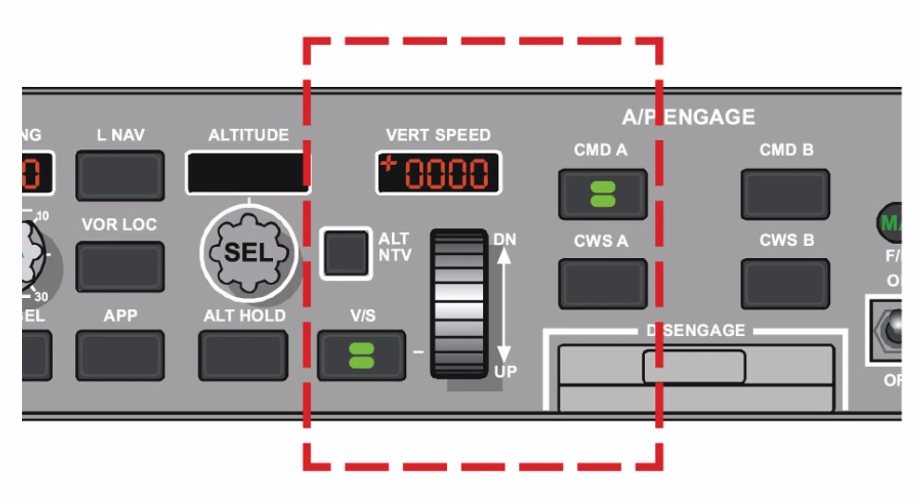
Altitude Acquire
- Selected on rotary knob
- Rate set using V/S
- On reaching, ALT HOLD engages
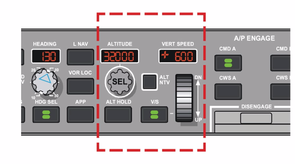
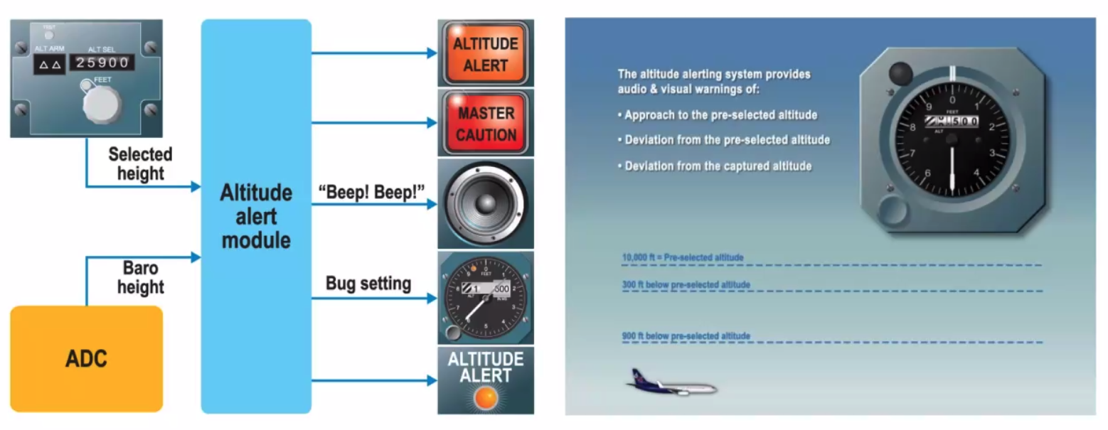
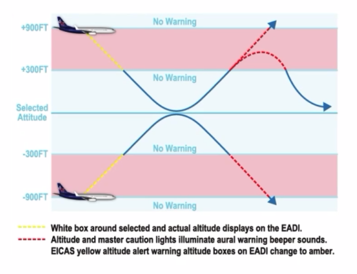
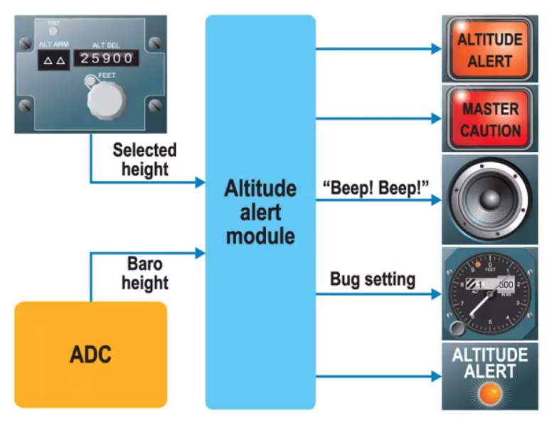
Altitude Alerting
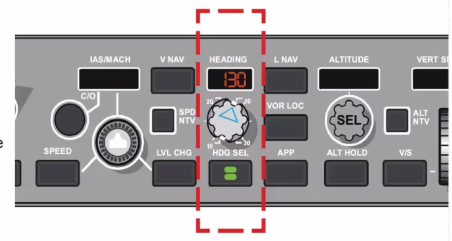
Heading Hold
- Pushlight selection
- Rotary Selection knob
- heading appears in window above
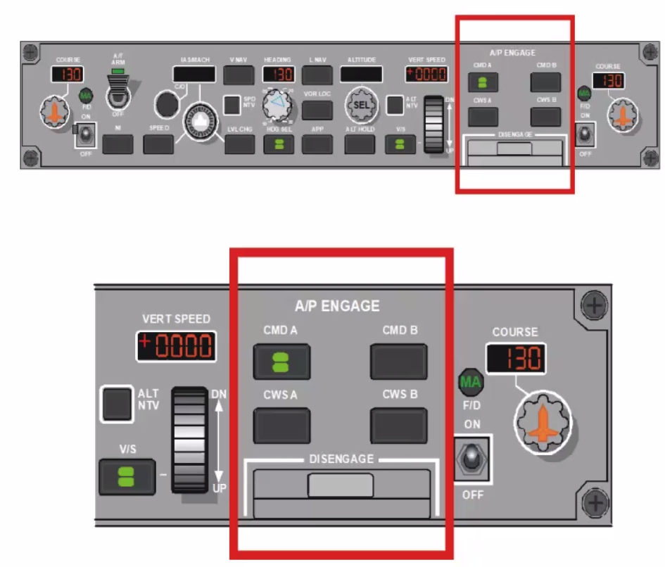
Approach Mode:
- APP pushlight selected
- Arms or Engages
- Other CMD (A/B) engaged
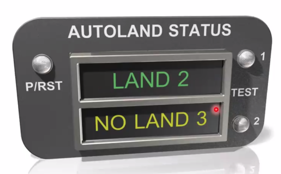
- Enables ‘Fail Passive’ for Autoland
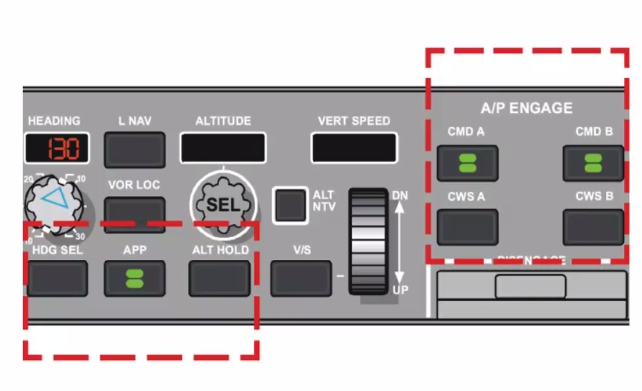
==Fail Operational - if you get a failure, you remain operational Fail Passive== - If we fail it will PASS back to you (not quite what it means but )
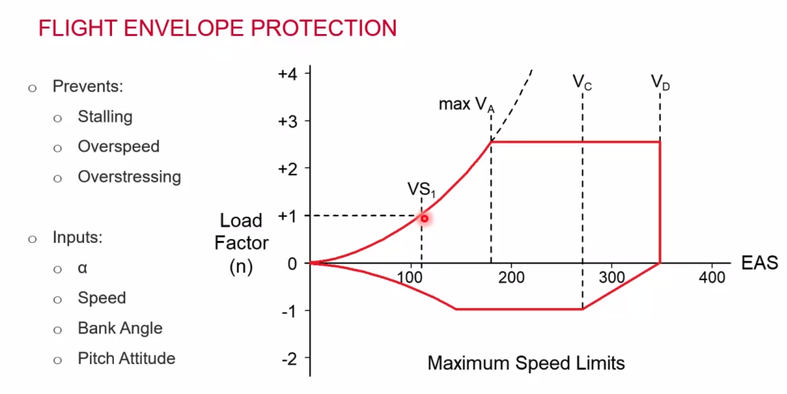
Flight Envelope Protection
Flight Management Computer Systems
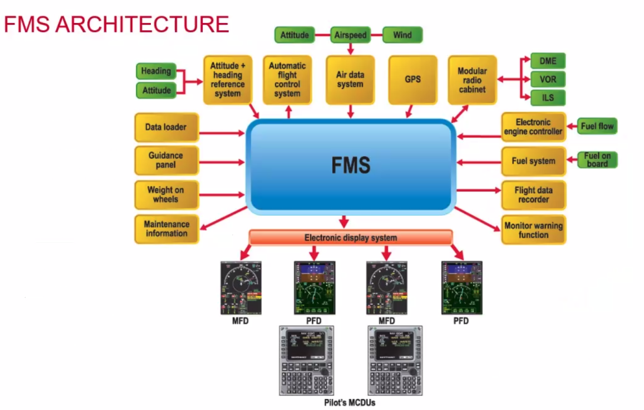
// The whole system is the FMS but the blue box SHOULD rather be labelled as FMC
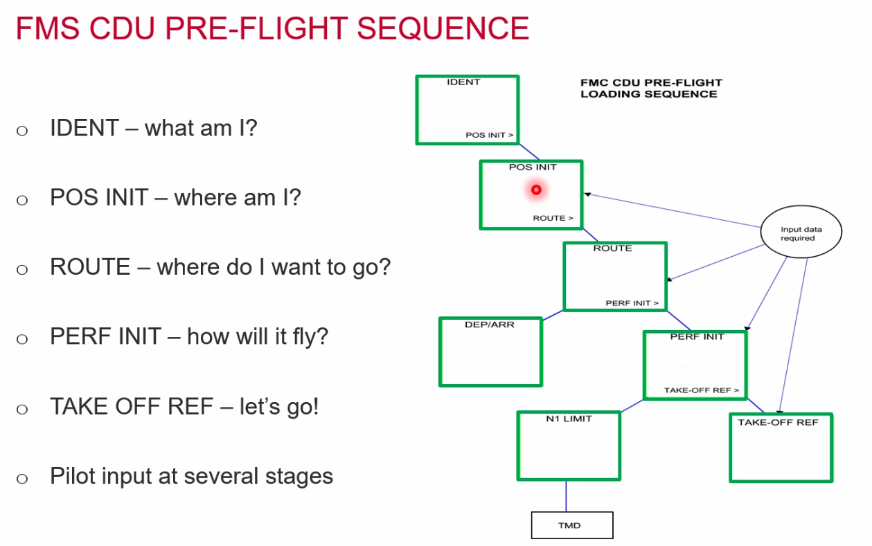
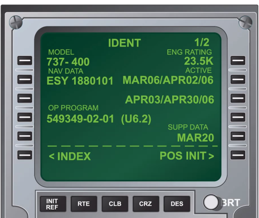
IDENT PAGE:
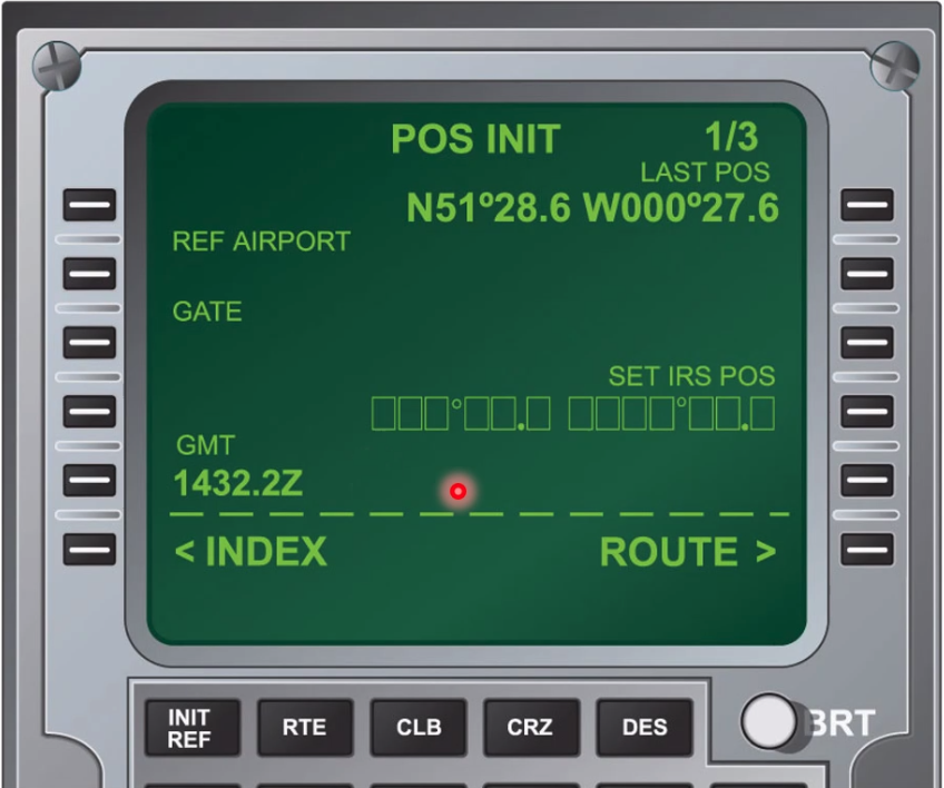
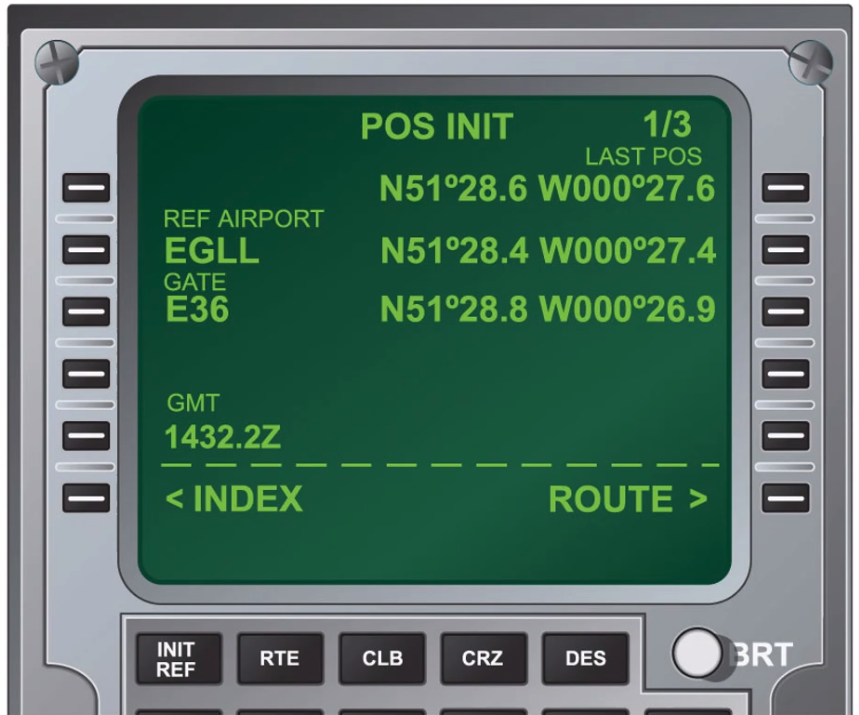
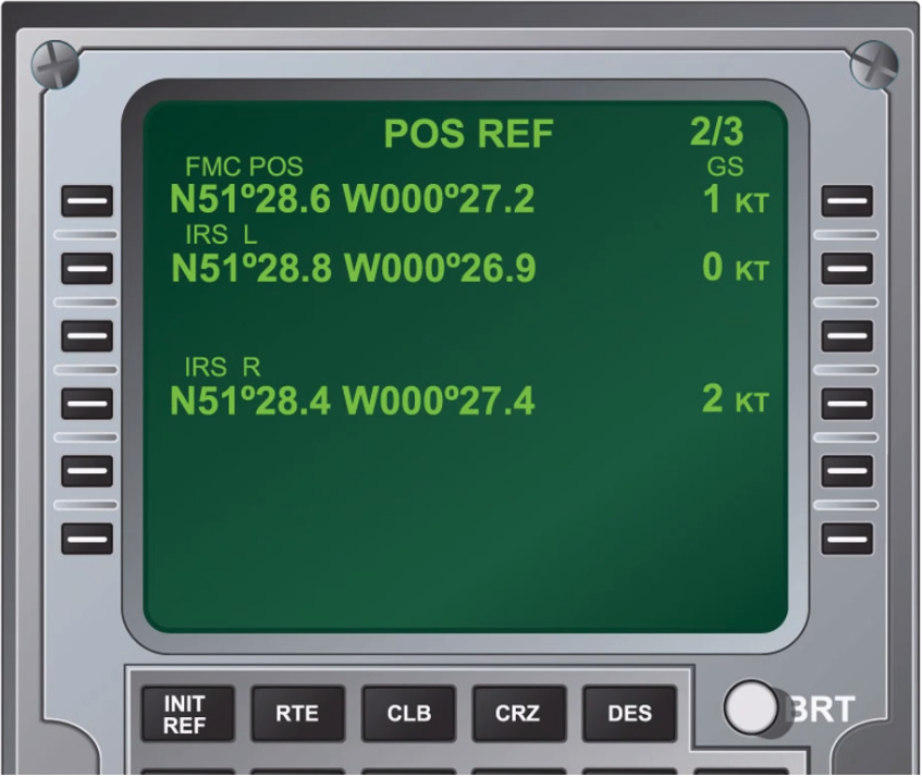
POS INIT:
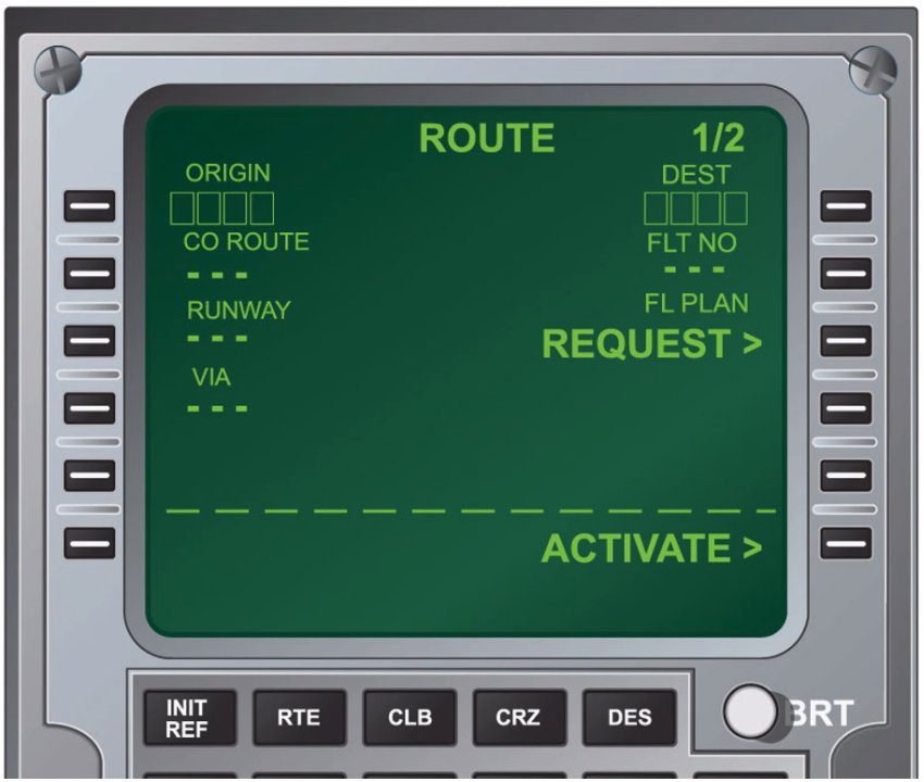
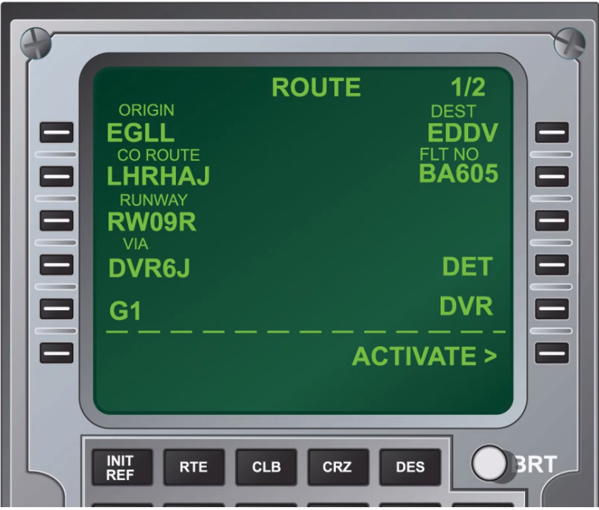
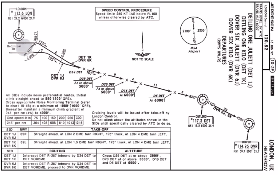
ROUTE:
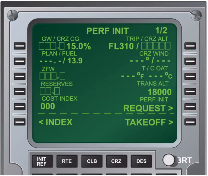
 PERF INIT:
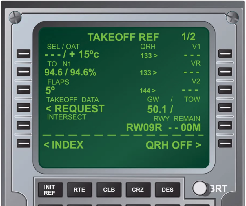
Takeoff Ref:
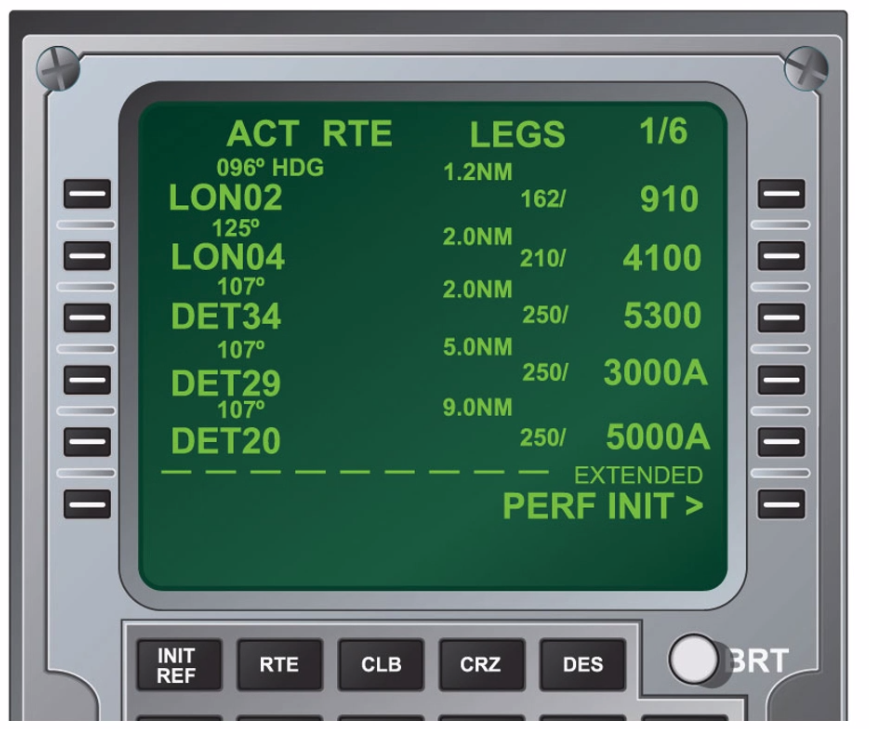
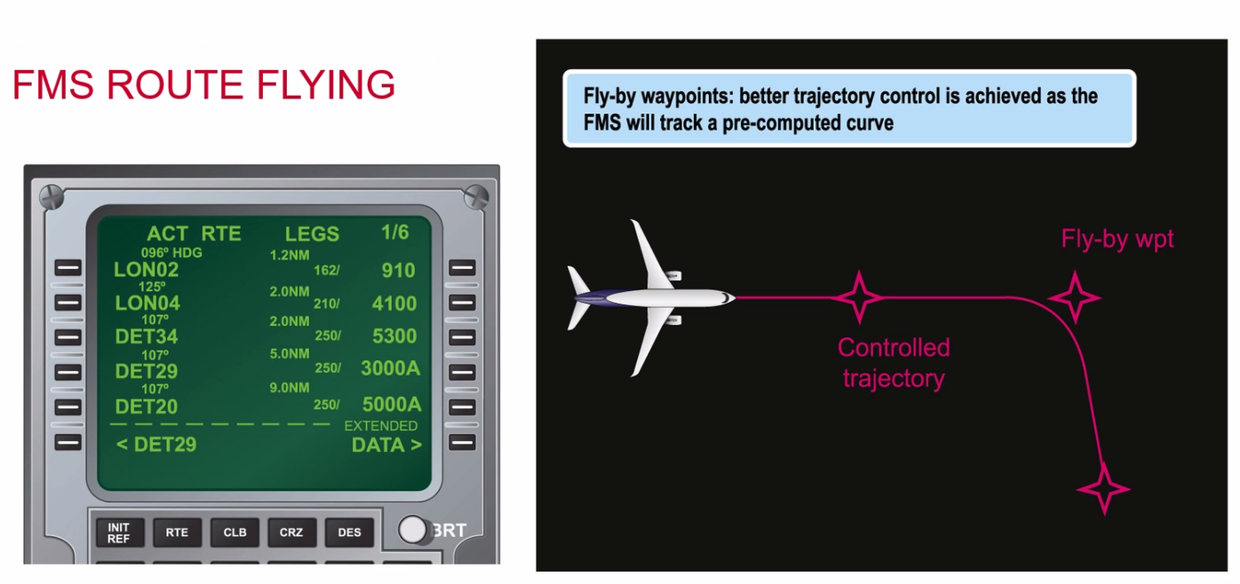
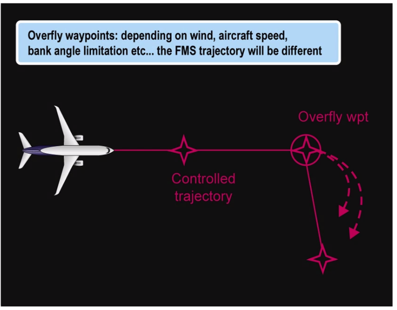
FMS Route Flying:
Inertial Navigation Systems
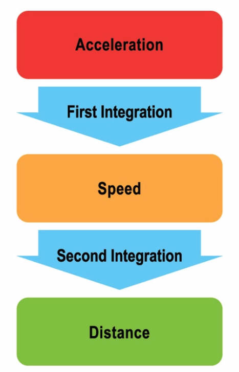
- Principle behind this isn’t complicated, it’s essentially just Speed = Distance / Time
- First integration - multiply acceleration x time = ==speed==
- Second integration - multiply speed x time = ==distance==
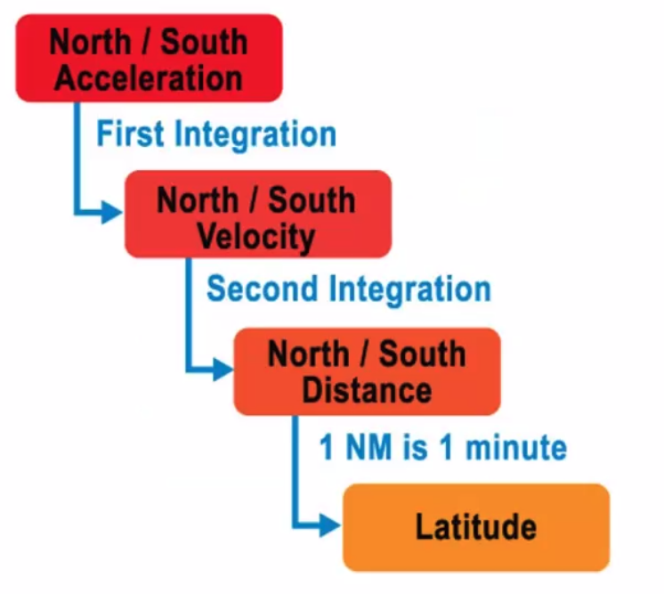
Calculating latitude change is easy, because we’re on a great circle. Because 1nm is 1minute of latitude and 60nm is 1 degree of latitude.
Longitudinal change is slightly harder because we will sense East/West acceleration.
- Integrate twice gives distances E/W Only at the equator
- Need to work out Change of Longitude from the DEPARTURE formula
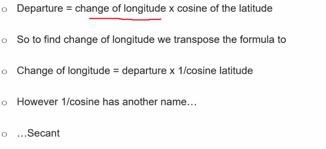
change of longitude = departure x secant of the latitude
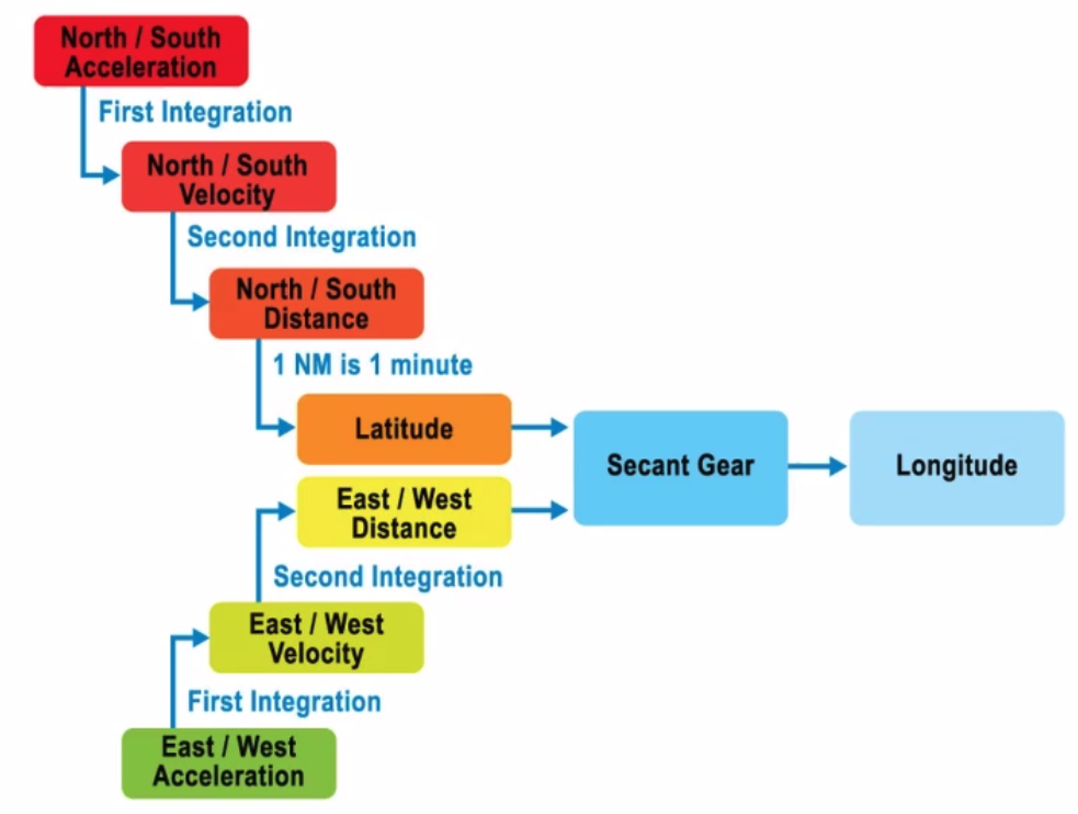
Early systems had an actual gear.
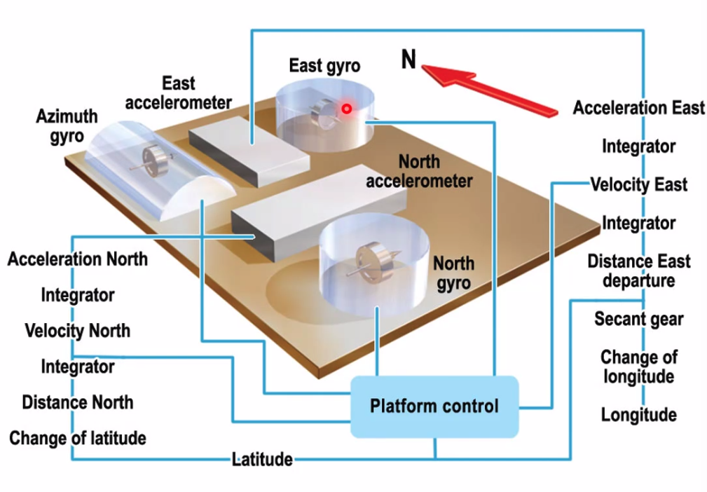
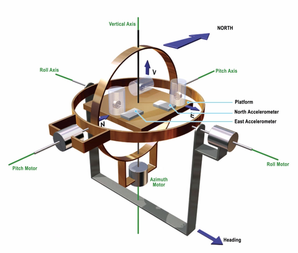
Stable Platform INS
- INS is a stable platform - stays level whilst the aircraft moves around it in a gimbal array
- East Gyro & North Gyro
- 2 accelerometers N/S and E/W
- Gyros N/S, E/W and Azimuth
- Platform finds level and N
- Stays N aligned and level - aircraft manoeuvres around it but the platform stays still.
Uses Rate Gyros (cans within cans)
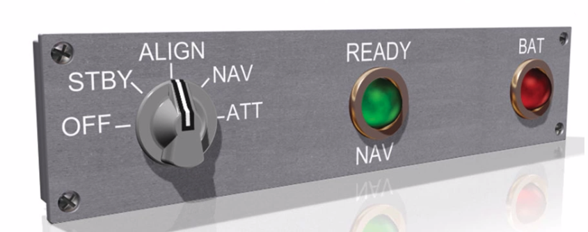
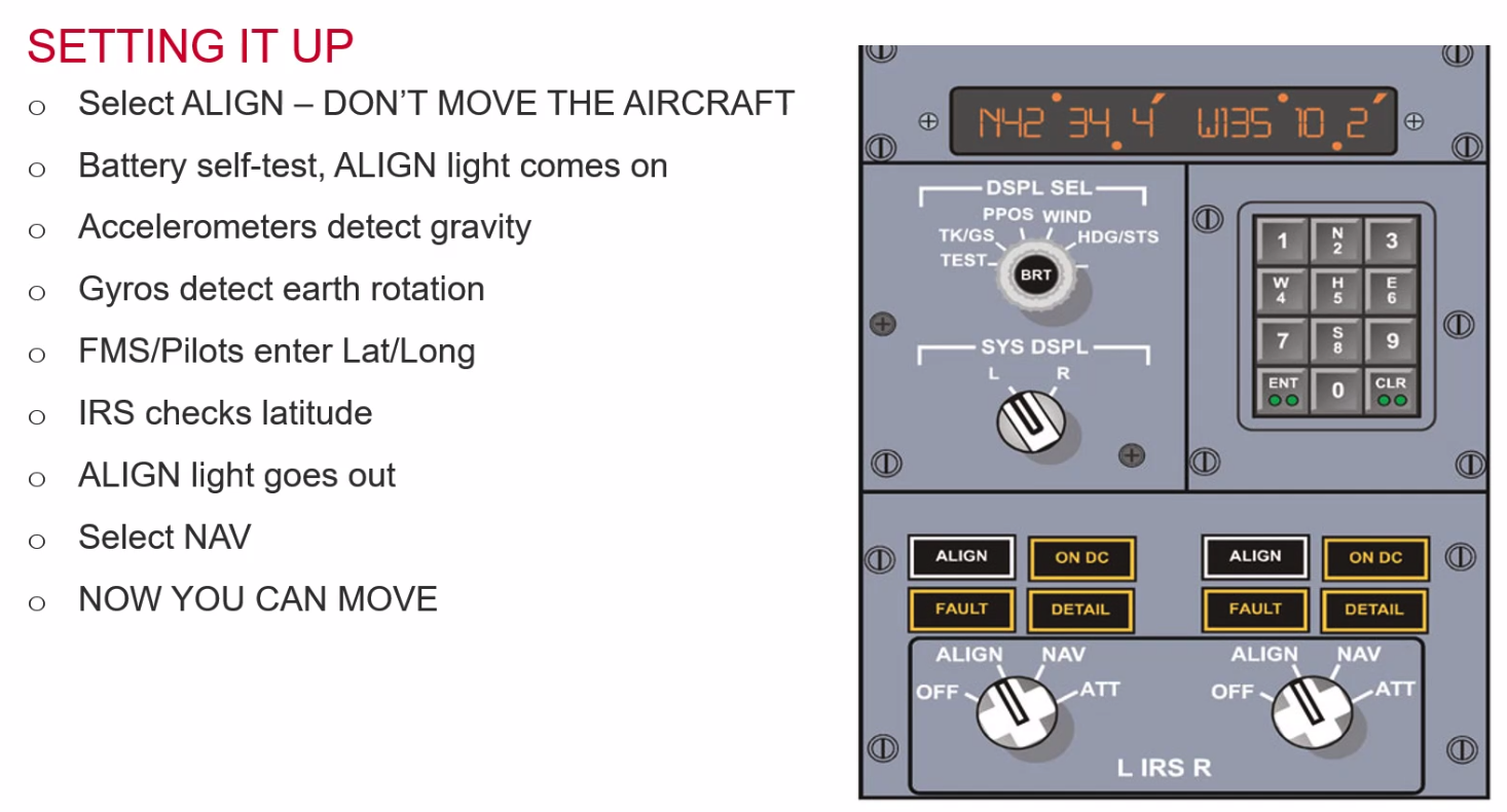
Setting it up:
- Off to stby to align - we cannot move whilst its aligning, 10 - 15 minutes, can be longer.
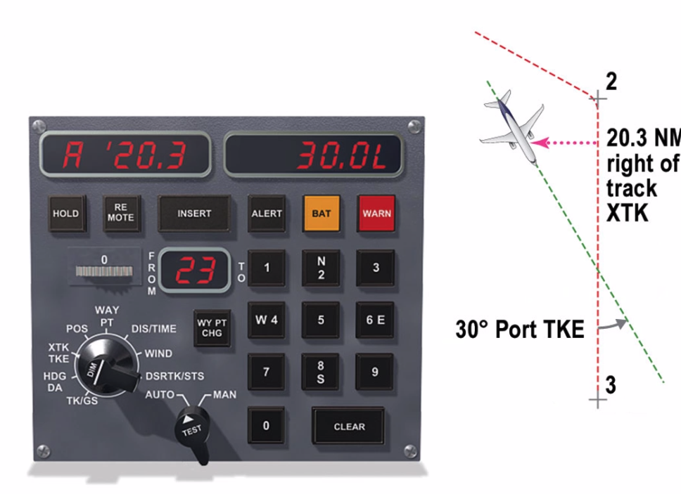
- Output selected on rotary knob
- track/gs
- heading/drift angle
If nav fails we can just select Attitude, but once we select attitude we cannot then go back to Nav (because we will be moving).
- could fail due to
- power failure
- battery data
- data corrupt
Inertial Reference System
Strap down systems - more modern
- don’t bother to align the platform with north, just sense it
- don’t need to keep it level
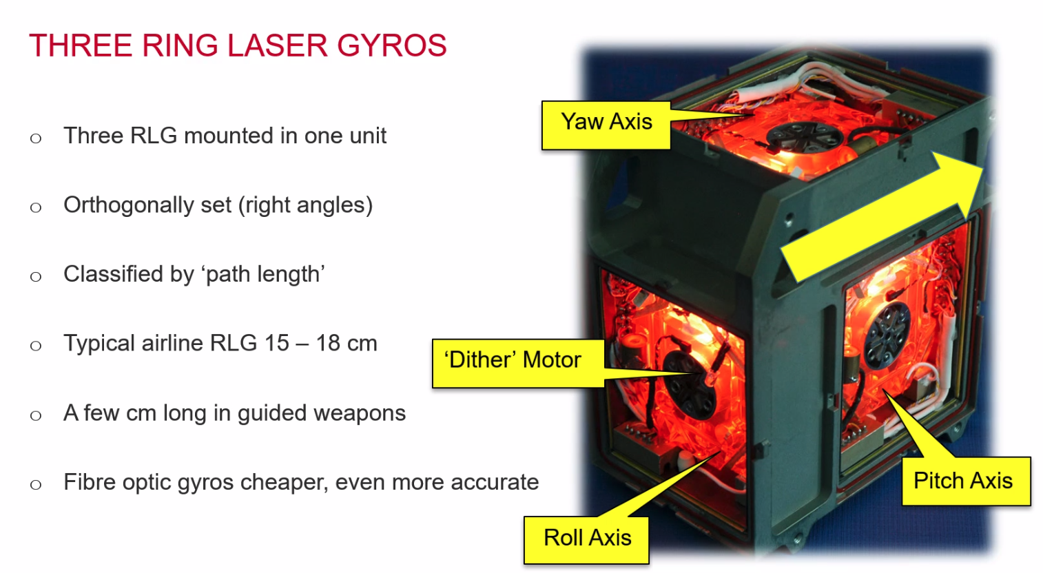
- senses roll, pitch and yaw
- IRS has 3 gyros - roll, pitch and yaw
- and 3 accelerometers
- Uses ring laser gyros
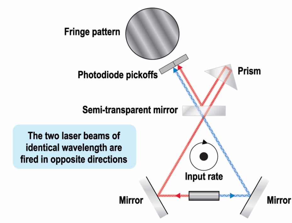
- laser split into two
- measures difference between the distance (red is a longer distance)
- Has a dither motor to keep it moving
- Can lock in at very low rates
RLG - a sick gaming computer
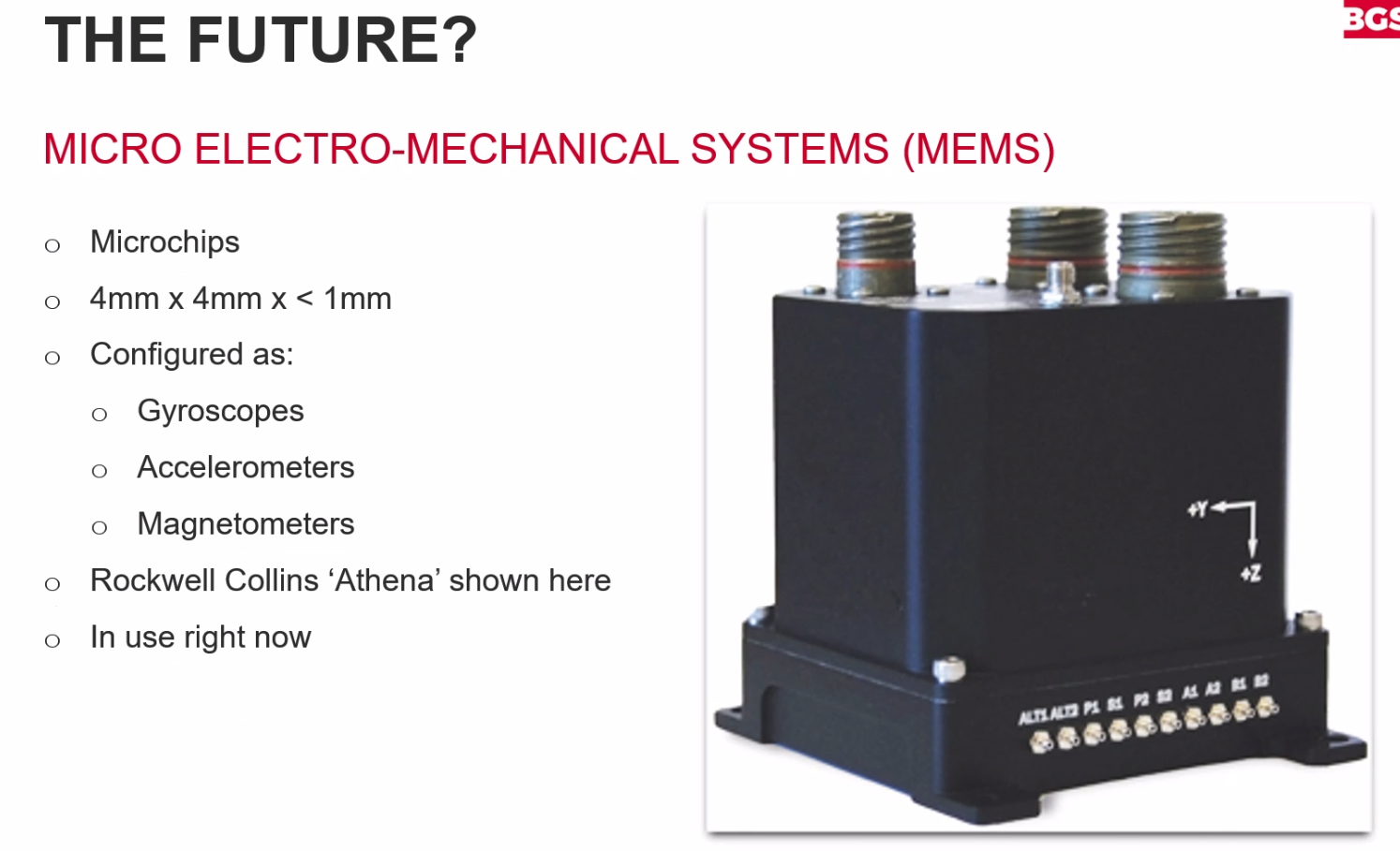
New Tech
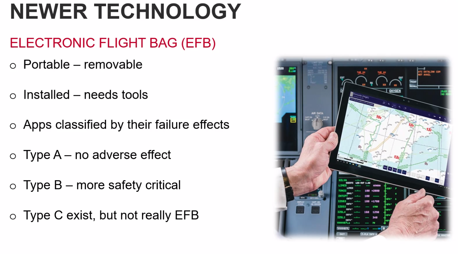
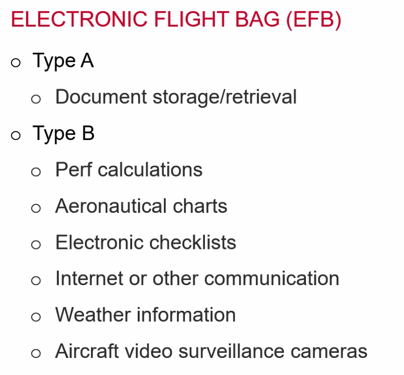
==Q. EFBs are classified into two categories for hardware certification== A. Portable and installed